
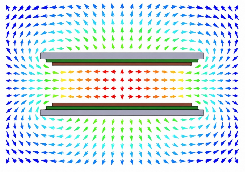
Wireless charging coil design: Balancing efficiency, size, and temperature
A wireless charging coil can achieve good coupling in perfect alignment and still overheat during operation. A compact coil may fit the available space but have higher resistance or weaker coupling. A larger coil or multicoil layout may tolerate more receiver displacement but require space the product cannot provide.
These constraints are connected. Coil dimensions, winding construction, air gap, alignment, ferrite, and nearby materials all affect power transfer and losses. Those losses influence both electrical efficiency and temperature.
This means that coil design cannot be evaluated from one result—or only at the ideal position. Engineers need to compare the complete design across its expected operating conditions.
Simulation makes that comparison possible before the geometry is committed to hardware.
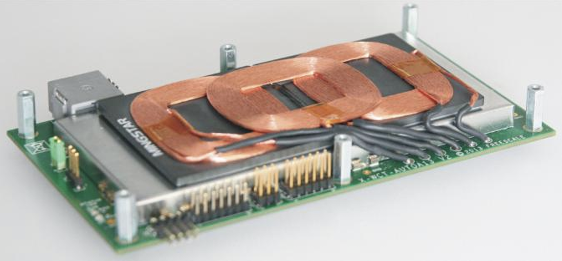
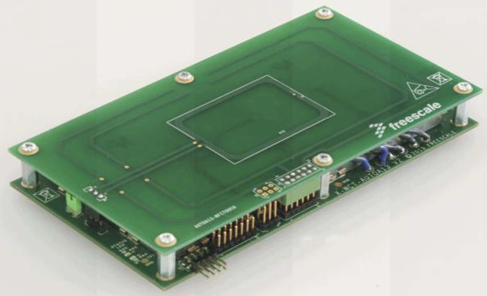
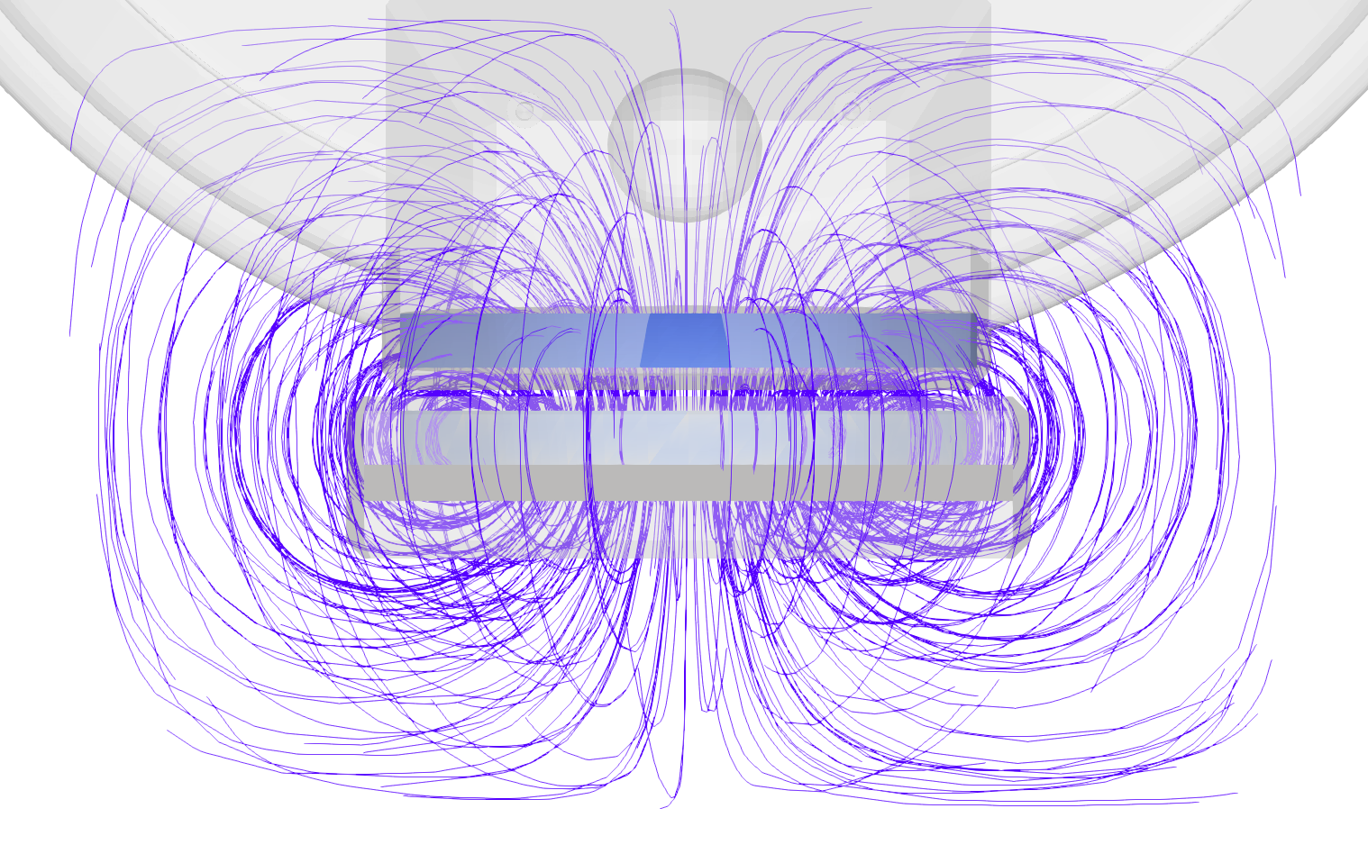
Description: The complete product assembly determines the electromagnetic and thermal operating conditions, not the coils alone.
The design changes when the coil enters the product
A transmitter and receiver may perform well when tested as an isolated, perfectly aligned pair. The result can change after they are integrated into the product.
The final assembly may introduce:
- a different air gap;
- lateral or angular misalignment;
- ferrite with limited coverage;
- magnets and mounting hardware;
- conductive housing components;
- restrictions on coil diameter and thickness;
- limited paths for removing heat.
Each change can affect coupling, inductance, resistance, losses, and circuit tuning. This is why evaluating only the nominal coil geometry can give an incomplete picture of the finished charging system.
Good centered performance is not enough
Coupling is usually highest when the transmitter and receiver are correctly aligned. Real products do not always operate in that position.
A phone may be placed off-center. An industrial robot may stop a few millimeters away from its nominal docking position. An e-bike or scooter may approach its charging point with variation in position or angle.
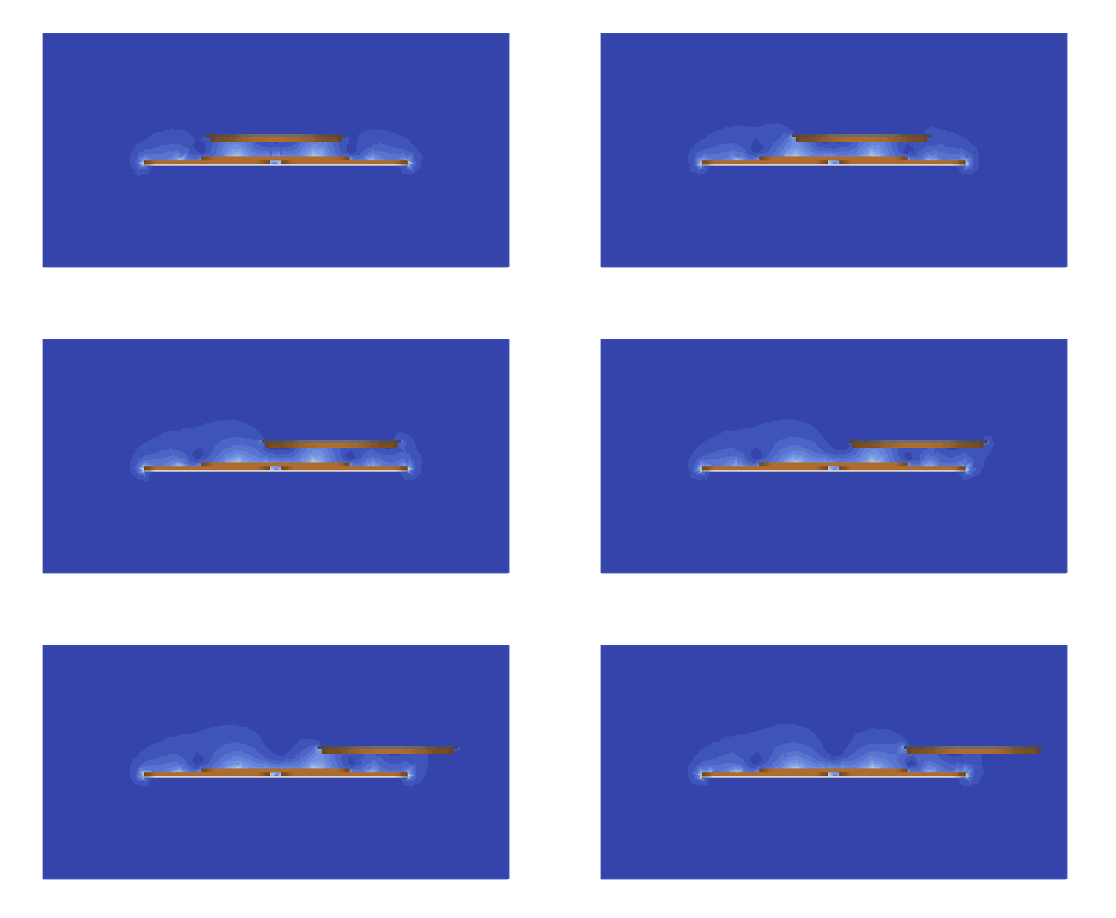
Simulation can evaluate the same design at several expected operating positions. Engineers can compare how displacement affects:
- coupling coefficient;
- mutual inductance;
- received power;
- electrical losses;
- coil current and voltage;
- component temperatures.
The objective is not necessarily to make performance identical at every position. It is to verify that the charger still transfers the required power and remains within its electrical and thermal limits throughout the acceptable operating range.
Here’s a simulation: testing the expected range of receiver positions helps identify where coupling falls, losses increase, or the required power can no longer be delivered.
Electrical losses become a thermal constraint
A design that transfers the required power may still be unsuitable if losses produce excessive temperature rise.
Losses can occur in the windings, ferrite, shields, backplates, and other nearby conductive components. Their distribution matters: an acceptable average temperature does not rule out a local hot spot.
Electromagnetic and thermal results should therefore be evaluated together. A CENOS model can help engineers connect:
- the magnetic-field and current distribution;
- the losses generated in individual components;
- the resulting temperature distribution over time.
This makes it possible to determine whether a thermal problem originates in the coil, ferrite, shielding, nearby metal, or another part of the assembly.
Description: a temperature field reveals where electromagnetic losses become a product-level thermal problem.
Different coil designs solve different problems
There is no universally best wireless charging coil.
A larger coil may provide better coupling for a particular receiver geometry but exceed the available package space. A PCB coil can offer a thin construction, while its trace geometry and copper thickness affect resistance and thermal performance. A multicoil transmitter can increase positioning freedom but adds conductors, switching requirements, and possible thermal interactions.
The relevant question is therefore not:
Which coil is best?
It is:
Which coil satisfies the power, size, alignment, and temperature requirements of this product?
Simulation allows candidate layouts to be compared under the same operating conditions. Depending on the design, engineers may vary:
- coil dimensions and position;
- number of turns;
- conductor or strand dimensions;
- ferrite geometry;
- air gap;
- receiver displacement;
- nearby conductive components;
- electrical operating conditions.
The results can then be evaluated against the actual product requirements rather than against one isolated performance value.
A real packaging and alignment problem
Tiler’s micromobility charging system illustrates why the product geometry matters. Its receiver is integrated into a vehicle kickstand, while the transmitter is installed in a pavement tile.
This arrangement limits the available receiver size and makes displacement part of normal operation. The design therefore cannot be evaluated only at one perfectly centered position.
According to the CENOS case study, the developed system achieved an average coupling coefficient of 0.5 and a Q factor above 700 across displacement equal to three times the receiver size. These results relate specifically to coupling and resonator performance; they should not be treated as a complete measure of system efficiency or thermal behavior.
The example nevertheless demonstrates an important point: simulation can be used to develop and assess a coil system within the mechanical and positional constraints of the real product.

Source: CENOS micromobility wireless charging case study
Compare the design before committing to hardware
Wireless charging coil design involves more than maximizing coupling at perfect alignment.
The selected design must:
- fit inside the product;
- deliver the required power;
- operate across the expected alignment range;
- avoid excessive losses;
- remain within component temperature limits;
- work with the intended circuit and surrounding materials.
CENOS Wireless Charging simulation brings the electromagnetic, circuit, and thermal parts of this comparison into one model. Engineers can test candidate geometries and operating positions, identify where losses occur, and assess temperature rise before committing to another hardware iteration.
The goal is not to find a perfect coil. It is to find a design that satisfies the requirements of the complete product.