
Induction coil design for heating uniformity: Trade-offs engineers need to see
A coil can deliver enough power and still heat the wrong area.
That is where many projects start going in the wrong direction. The engineer sees that the part is heating, so the first instinct is to add power, add turns, or make the coil larger. Sometimes that helps. Very often it only moves the problem. One region improves, another falls behind, and the process becomes harder to control.
Uniformity work is usually not about finding one perfect coil. It is about choosing the right compromise. A change that improves edge heating may weaken the center. A change that increases coupling may also increase sensitivity to gap and alignment. A field picture may look acceptable, while the temperature history at two points tells a less pleasant story.
The examples below use the CENOS cooktop case, the coil design case, and the documentation on circuits, closed coils, and results analysis. The cooktop case makes the problem very visible, but the same design logic applies to industrial heating, hardening, preheating, and similar induction processes.
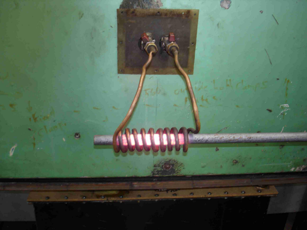
A real induction heating setup with a copper work coil around a metal bar.
The point is simple: heating pattern comes from alternating magnetic field shape and coupling, not from power level alone. A coil can couple strongly to a workpiece and still create the wrong local temperature distribution.
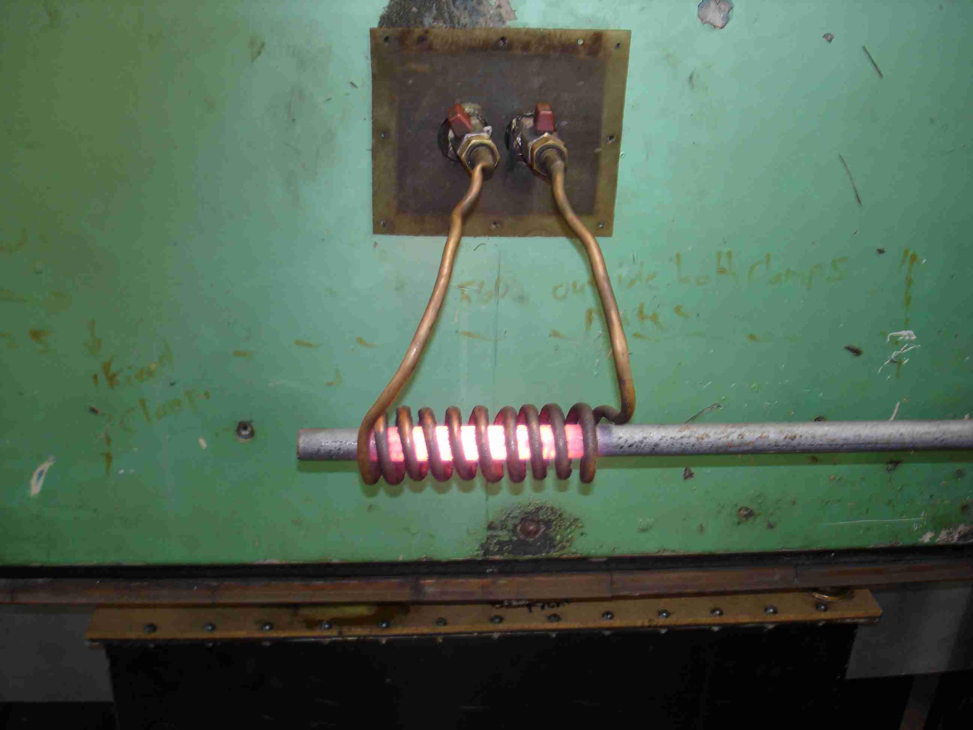
Source: Wikimedia Commons, Induction heating of bar.jpg.
Trade-off 1: Coil footprint vs heated area
Main point: A coil can heat efficiently and still miss part of the area that needs uniform temperature.
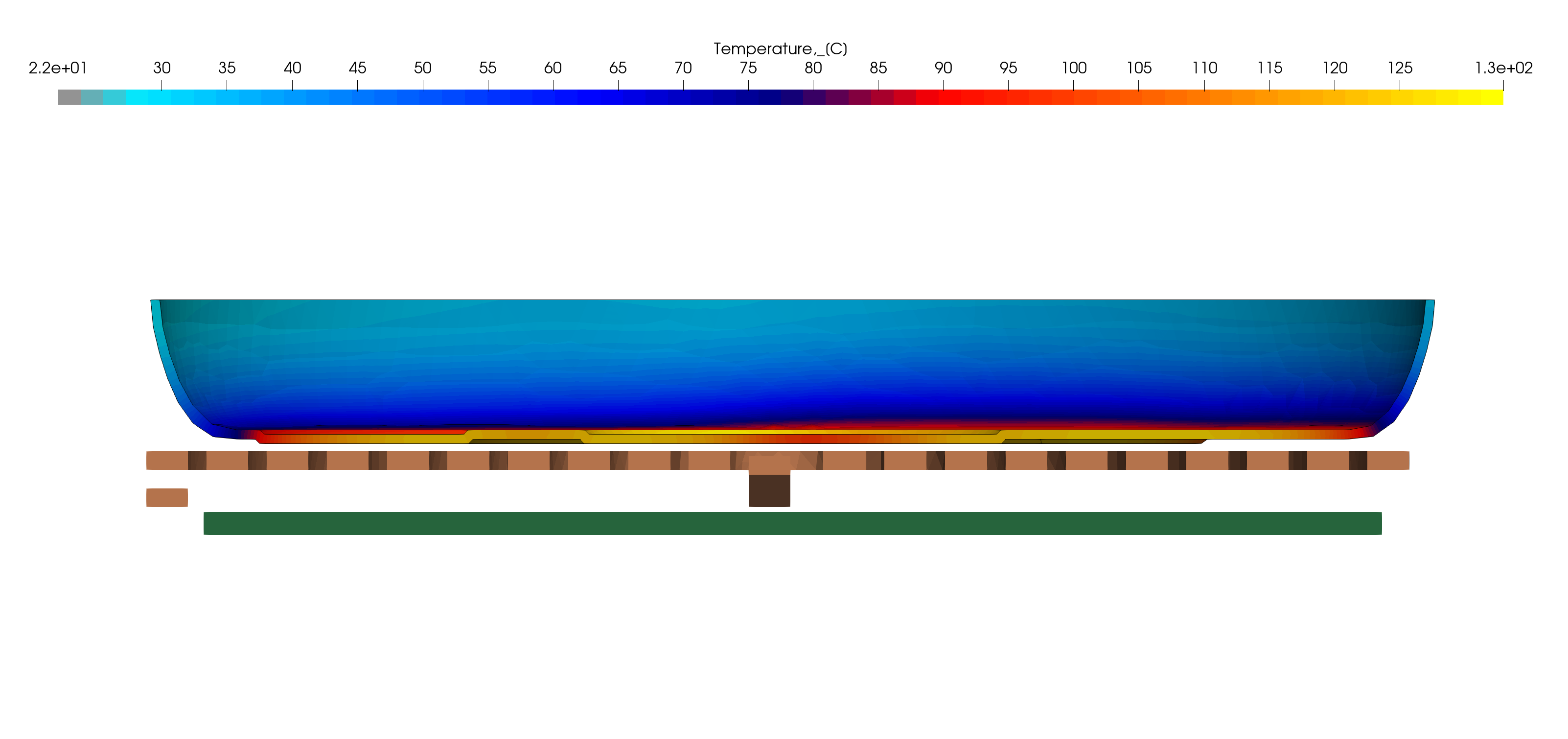
Most uniformity problems start with a mismatch between the active coil area and the area that needs heat. In the CENOS cooktop case, the pan is heating, but not evenly. The simulation cross-section shows that heat is concentrated in one band above the active coil region, while the rest of the pan base remains cooler.
This is one of the first things engineers should check. Not whether the model gets hot, but where the energy enters the workpiece and which regions are still left behind. That sounds obvious, but in practice teams often look at overall temperature rise first and only later notice that the heating footprint is too narrow or misplaced.
Cross-section temperature result from the CENOS cooktop case.
The hottest band forms near the lower active region of the pan base, while large parts of the pan remain cooler. This shows that the coil footprint and the real heating target are not fully aligned.
Inspect the temperature distribution at several times during the heating cycle, not only at the end. Early results are influenced strongly by where electromagnetic losses are generated, while later results also reflect heat conduction through the workpiece. Comparing both can help determine whether non-uniformity originates primarily from the coil’s power-deposition pattern or from the subsequent thermal response.
Trade-off 2: Better edge coverage vs center heating
Main point: Moving energy outward can fix a cold outer zone, but it often reduces heating intensity where the process was already working well.
Once engineers notice a cold outer region, the next step is usually to push the field outward. That can be the right move, but it is never free. Better edge coverage may reduce center heating, make the field wider than needed, or increase process sensitivity to position and gap.
This is where coil design becomes a real engineering decision instead of a geometric clean-up job. The goal is not to make the temperature map look balanced at one moment. The goal is to decide which regions need more energy, which regions must not overheat, and how much variation the process can tolerate in real production.
Coil and pan base interaction from the cooktop case. This view helps compare the physical coil coverage with the part of the pan that must be heated. It is a direct way to see whether the active area is too narrow, too concentrated, or misplaced for the job.
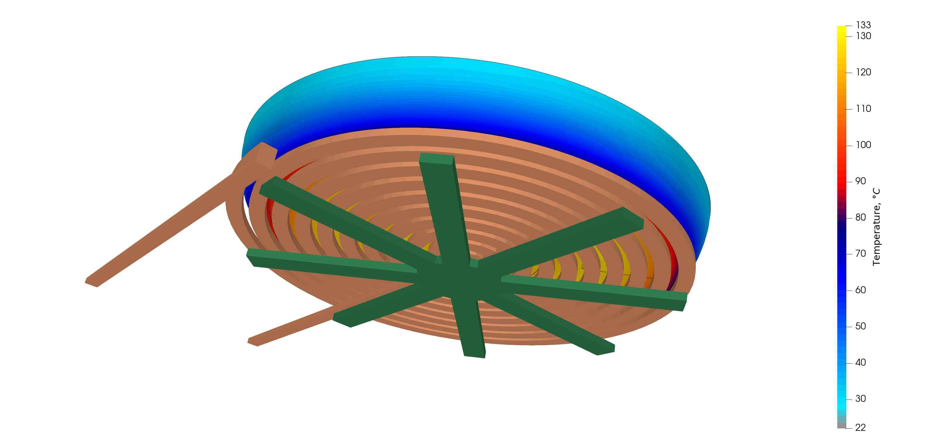
The same logic applies well beyond cooktops. In hardening, brazing, billet heating, and preheating, the target region changes, but the design question stays the same: how do you increase heating where it is needed without creating a new hot spot next to it?
Trade-off 3: Stronger coupling vs lower field leakage
Main point: Leakage is not only an efficiency issue. It also changes where useful magnetic field is missing.
Field leakage is often discussed as wasted power, and that is true, but it is only half of the problem. Leakage also means the useful field is not concentrated as well as it could be in the workpiece. When that happens, uniformity suffers, not just efficiency.
In some designs, the coil couples strongly enough to reach the target temperature, but a noticeable part of the field still spreads outward into air or into regions that do not support the intended heating pattern. That can create larger local gradients and make the result less stable when the part position, gap, or surrounding geometry changes.
Magnetic field lines from the cooktop case. The denser field under the pan is the useful part. The field that spreads farther into the air is a sign that the geometry is not directing all magnetic energy where it is needed.
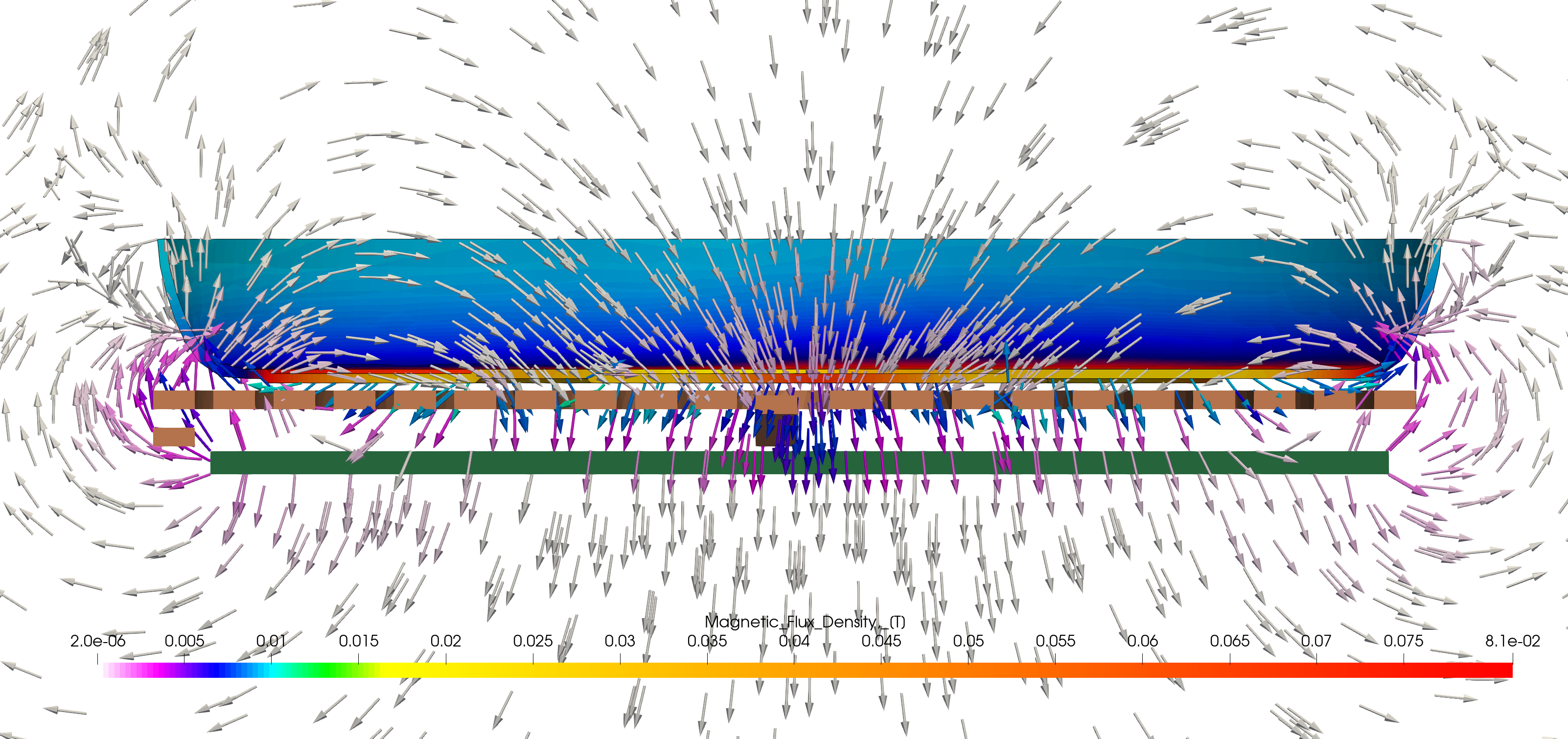
This is why a coil can look mechanically reasonable and still be weak from a heating uniformity point of view. The copper shape may be fine to manufacture. The power source may be fine. But the field is still not going where the process needs it to go.
Trade-off 4: Good-looking heat map vs real temperature history
Main point: A smooth color map can hide a temperature split that keeps growing during the cycle.
Color plots are useful, but they can also be misleading when used alone. A result may look acceptable in one frame while two important locations on the workpiece are separating over time. This is why time history matters.
In the cooktop case, the temperature-time result makes that clear. The offset-middle point heats faster than the center and stays ahead during the cycle. That gives a direct numerical confirmation of what the cross-section already suggested.
Temperature-time diagram from the cooktop case. The two curves do not stay together. One location on the pan warms faster and reaches a higher temperature earlier. This turns a visual impression of uneven heating into a measurable engineering problem.
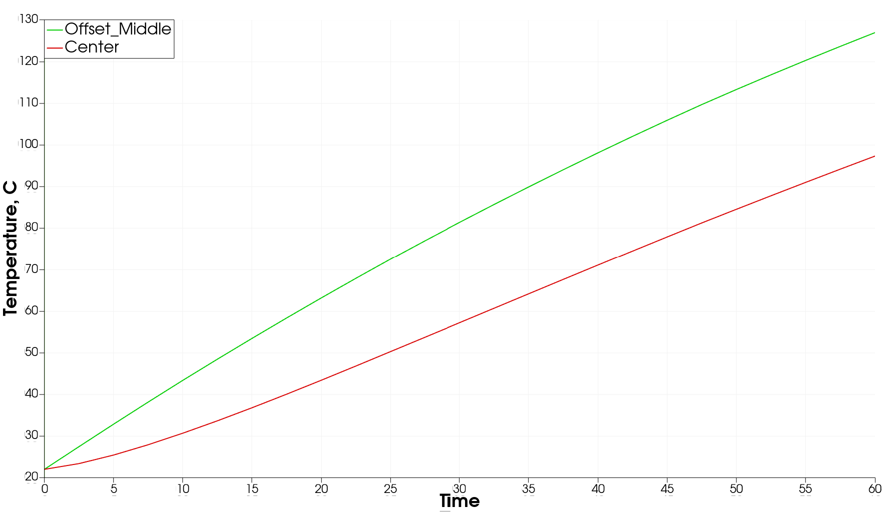
A practical lesson here is simple. Before changing hardware, check whether the temperature difference is temporary or whether it keeps growing throughout the cycle. If it keeps growing, the field distribution usually needs real adjustment. Waiting longer rarely fixes the pattern. It just makes the hotter region even happier and the colder region still late to the party.
Trade-off 5: Visible coil shape vs real current path
Main point: Two coils that look similar in CAD can behave differently if the current path and circuit definition are different.
Uniformity is not controlled only by the visible coil shape. It is also controlled by how current moves through that shape. Two designs can look similar in CAD and still produce different heating if branch definition, parallel paths, or input conditions are different.
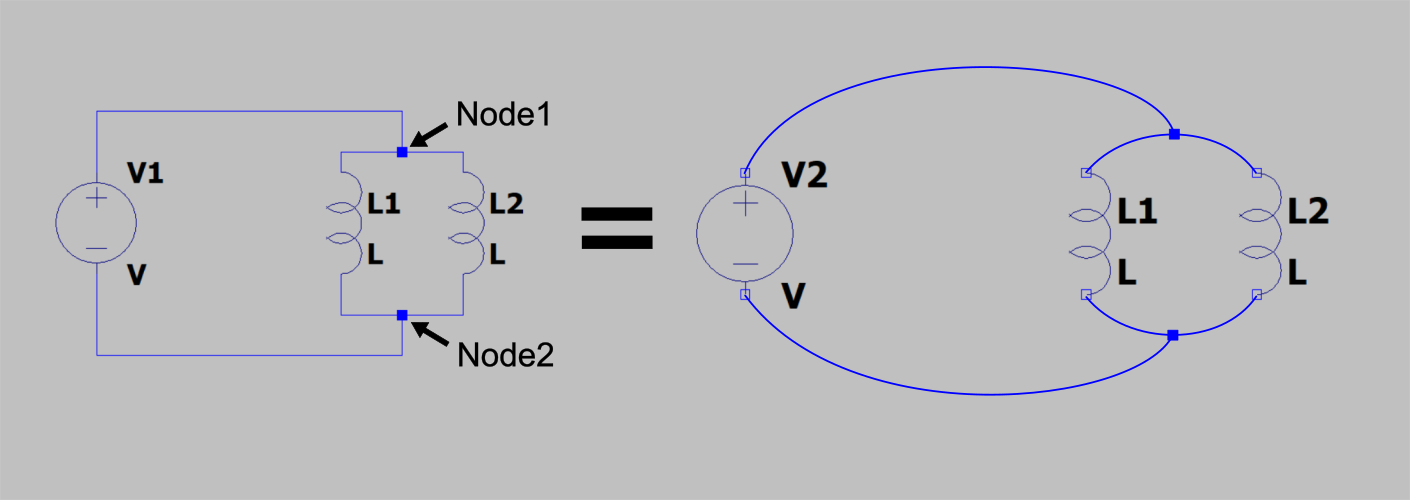
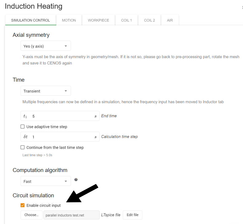
This is why the CENOS documentation on circuit definition matters in a coil uniformity article. CENOS supports circuit definition through a netlist file, including a power source, coils, and passive components such as resistors. That allows the engineer to model how the coil is actually driven instead of assuming a simplified input that may not match the real setup.
Circuit node explanation from the CENOS circuits documentation. This is the basis for defining how current is distributed in the model. For uniformity work, that matters because current path changes the magnetic field, and the magnetic field changes where heat is generated.
Circuit input setup in CENOS. This is the step where the model is tied to the real driving conditions of the coil. If the circuit input is wrong, the field and heating result can be wrong even when the visible coil geometry is correct.
If the physical setup has multiple branches or multiple coils, it is risky to treat it like one generic source. A wrong current split can give a very convincing but wrong field picture. Then geometry gets blamed for a problem that was electrical from the beginning. That is a classic way to waste time and copper.
Trade-off 6: Simple CAD representation vs physically correct coil model
Main point: A neat solid model is not enough when the real inductor is multi-turn and its effective electromagnetic behavior depends on how it is defined.
Another point that quietly changes uniformity is how the coil is represented in the model. The CENOS closed-coils documentation makes an important distinction between single-turn and multi-turn coils. It sounds basic, but it matters a lot when a real coil is simplified into one solid CAD body.
A solid body that represents many turns is not the same as one copper loop. In a multi-turn representation, turn count, fill factor, and cross-sectional area affect the effective behavior of the inductor. If these values are guessed or skipped, the model can still produce a clean image while missing the real current density and coupling behavior.
Closed coil inductor setup in CENOS. This is where the engineer defines whether the model behaves as a single-turn or a multi-turn coil and sets the main inductor conditions. That choice affects how the solver interprets the inductor and therefore changes field and heating pattern.
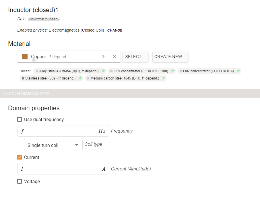
Fill factor and cross-sectional area example referenced from the closed-coils documentation. This definition matters when a solid model stands in for many windings. The outside geometry may look unchanged, but the effective electromagnetic behavior does not stay the same if these values change.

This is one of the less obvious points in uniformity work. The copper outline alone is not the full design. The model has to know what that copper actually stands for.
Trade-off 7: One result image vs a full diagnostic read
Main point: One screenshot may show where the problem is, but it usually does not show why it happens.
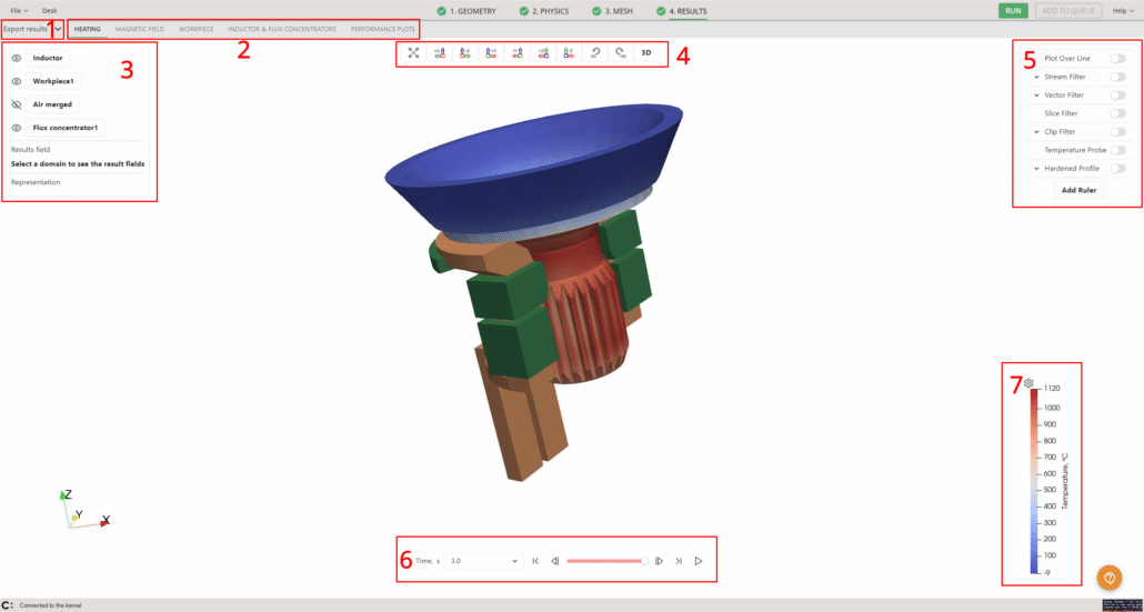
The IH Results Viewer documentation is useful here because it shows how engineers should read a coil design, not just how to make a screenshot. CENOS includes separate tabs for heating, magnetic field, workpiece, inductor and flux concentrators, and performance plots. It also includes filters such as plot over line, stream filter, vector filter, slice, clip, and temperature probes.
That matters because a single image almost never explains the whole problem. A heat map shows where the result is good or bad. A field view helps explain why. A line plot or probe then shows whether the difference is sharp, gradual, stable, or growing with time.
Overview of the IH Results Viewer. The point is not the interface itself. The point is that engineers can move between heating, magnetic field, and plot-based analysis instead of judging a coil from one image alone.
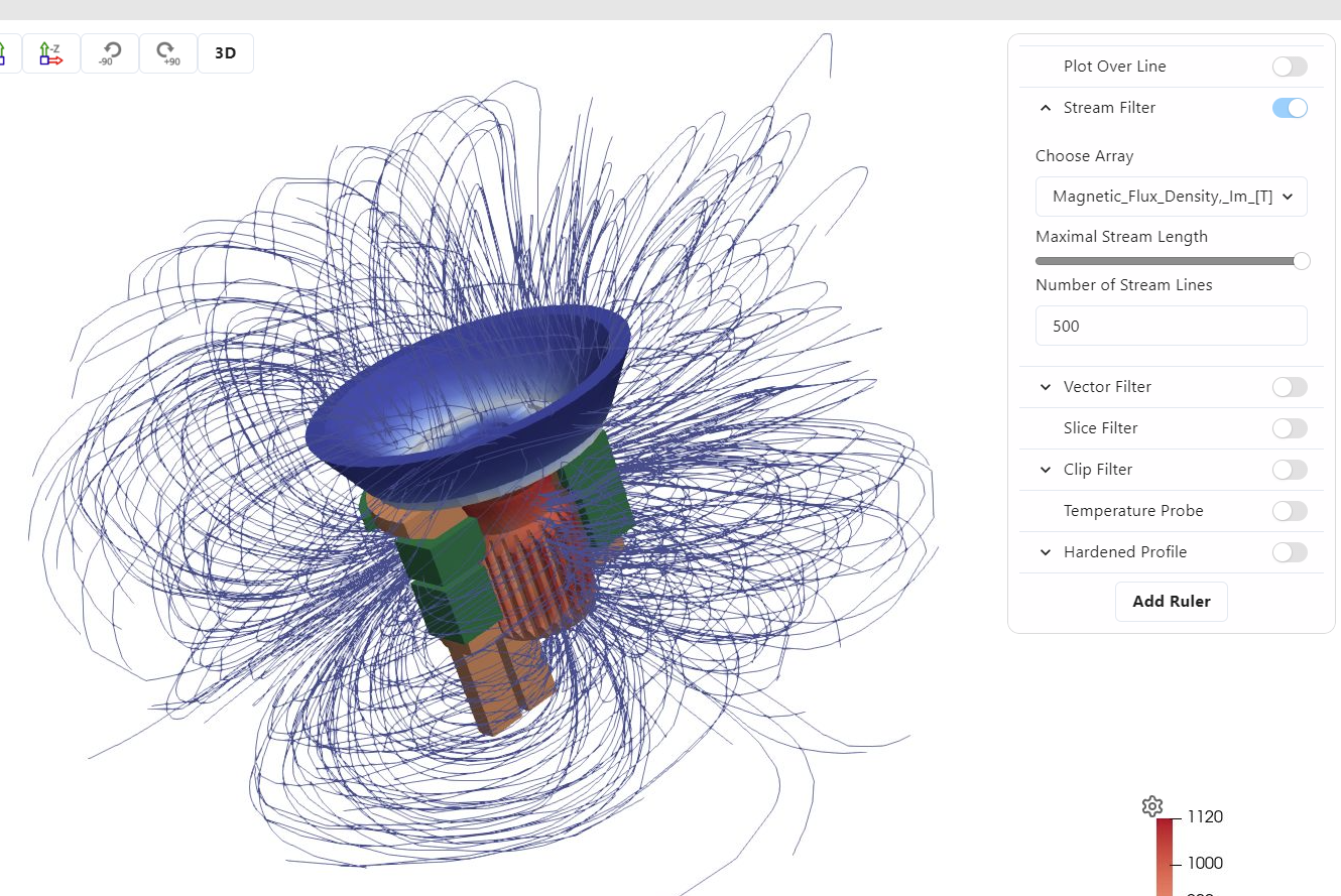
Streamline view of the magnetic field in the IH Results Viewer. This helps explain field concentration and leakage around the geometry. It is especially useful when a temperature plot shows a problem but does not explain where the field is going.
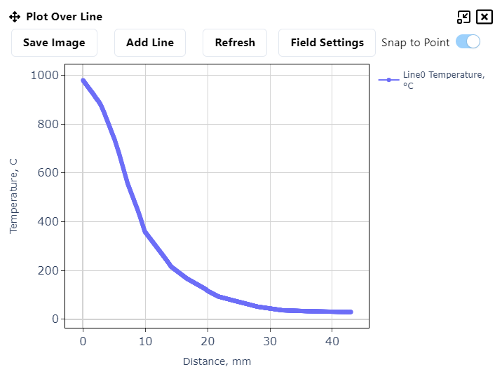
Plot over line result in the IH Results Viewer. This turns a color gradient into an actual distribution along a selected path. It helps answer a practical question: how sharp is the temperature drop, and where does it begin?
A good review sequence is straightforward: first check where the temperature is high and low, then check where the field is concentrated or escaping, then check one or two line or point plots. That usually shows whether the next change should be geometry, current path, coil representation, or process settings.
Conclusion
Heating uniformity is not solved by chasing one ideal coil shape. It is solved by reading the trade-offs correctly.
The CENOS examples make that point from several directions. The cooktop case shows that one area can heat well while another still lags. The circuits documentation shows that electrical definition can change the field even when the coil outline looks the same. The closed-coils documentation shows that a solid CAD body does not contain enough information by itself when the real inductor is multi-turn. And the Results Viewer documentation shows why one heat map is never enough for making design decisions.
That is the real message behind coil design for heating uniformity. A change that helps one zone can hurt another. A design that improves coupling can increase sensitivity. A result that looks smooth can still hide a growing temperature split. The useful coil is not the one that looks best on screen. It is the one that gives the right thermal result in the right zone, with the right stability, before the next piece of copper is built.
Sources used in this article
- CENOS Induction Heating documentation hub
- CENOS: Optimizing induction coil design case study
- CENOS: The challenges of induction heating for cooktops case study
- CENOS documentation: Defining circuits
- CENOS documentation: Closed coils simulations
- CENOS documentation: IH Results Viewer
- Wikimedia Commons: Induction heating of bar.jpg