
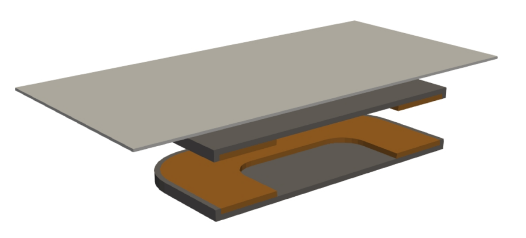
Electromagnetic interference in WPT: mitigating losses from metallic backplates
Perfectly designed transmitter (Tx) and receiver (Rx) coils do not guarantee high wireless power transfer (WPT) efficiency.
Even with correctly tuned circuits, performance often drops when the coils are assembled into the final product. The root cause is usually nearby metallic and magnetic parts—such as metal backplates, alignment magnets, battery casings, and chassis screws. These surrounding components distort the magnetic field, lower the coupling coefficient, and create eddy currents that generate unwanted heat.
This article examines how these nearby structural materials reduce WPT efficiency, and demonstrates how CENOS: WCH software can predict and fix these system-level losses before you build a physical prototype.
Parasitic coupling and electromagnetic losses
In WPT systems, efficiency depends on maximizing the magnetic connection (flux linkage) between the Tx and Rx coils. However, when the alternating magnetic field hits nearby metal parts, those structures act like unwanted short circuits. This creates eddy currents inside the metal, which waste energy as heat and push back against the main magnetic field (Lenz’s Law).
This interference fundamentally changes how the system behaves, resulting in:
- Reduced coupling: Weaker mutual inductance and a lower coupling coefficient.
- Circuit detuning: Changes in self-inductance that cause an impedance mismatch in the tuned circuit.
- Higher resistance: Increased AC resistance and equivalent series resistance.
- Lower efficiency: A significant drop in the system’s quality factor along with higher power losses.
Because nearby metal parts actively change the magnetic field, basic two-coil models are not enough. Reliable design validation requires simulating the complete product assembly to capture these real-world interactions.
Simulation requirements
To properly evaluate a WPT system, engineers must look at the complete assembly rather than isolated coils. To predict real-world performance, the model must include every part that interacts with the magnetic field.
A complete simulation setup needs to define:
- Core components: Tx/Rx coils and ferrite shields.
- Surrounding hardware: Metal backplates, alignment magnets, fasteners, and conductive housings.
- Positioning: The primary air gap, plus different misalignment scenarios.
- Operating conditions: Thermal limits and active circuit loads.
Interference from surrounding metal is a multi-physics problem. Electromagnetic losses directly affect the rest of the system: eddy currents create thermal hotspots, and changes in inductance detune the circuit. CENOS: WCH is built to handle these connected problems by offering combined electromagnetic, thermal, and circuit simulation. This allows engineers to evaluate the final product design in software before building a physical prototype.
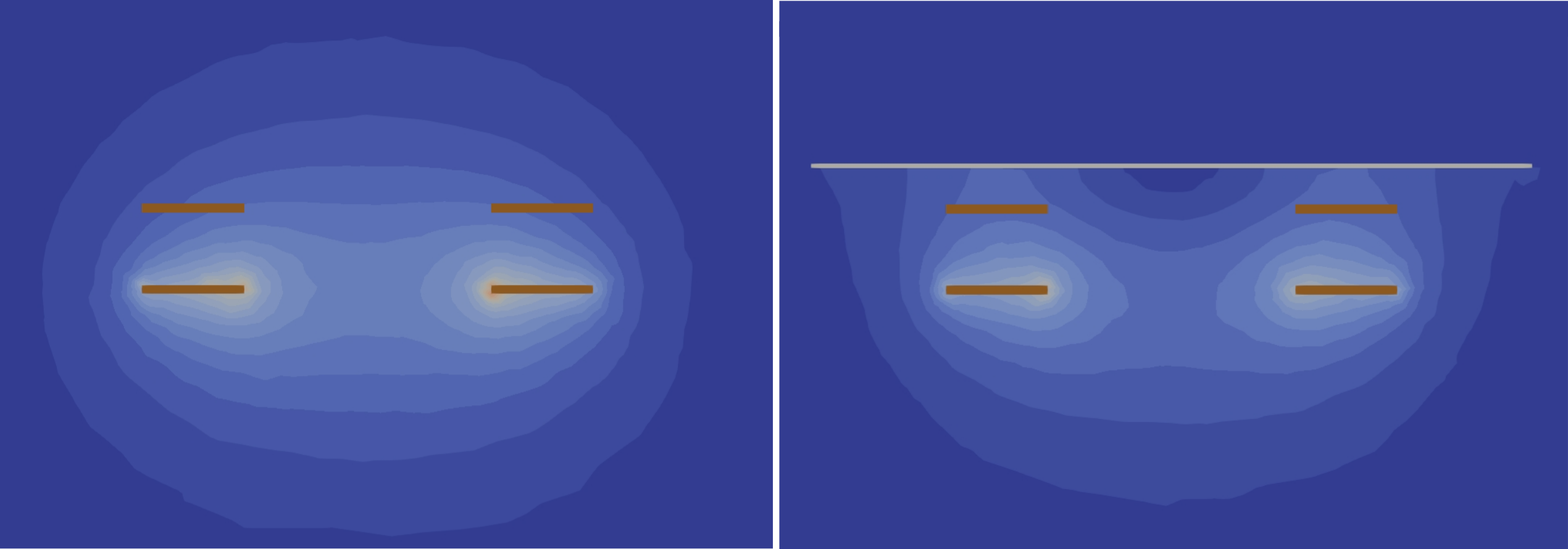
Image 1 – Open coil magnetic field without (left) and with (right) a metal backplate.
The role of magnetic shielding
To stop the magnetic field from leaking into nearby metal parts, engineers use magnetic shields, typically made of ferrite or nanocrystalline materials. Because these materials have high magnetic permeability, they provide an easy path (low reluctance) for the magnetic flux to follow. Instead of spilling over into the battery casing or chassis, the magnetic field is guided exactly where it needs to go.
Proper shielding serves a double purpose:
- Blocks interference: It protects surrounding structural metals from absorbing energy, preventing unwanted eddy currents and heat.
- Boosts efficiency: It improves the coupling coefficient by redirecting more of the magnetic field toward the receiving coil.
However, designing the shield takes careful tuning. If a ferrite shield is too thin, it can become magnetically saturated—meaning it cannot carry any more flux—and the field will leak right through it. If it is too thick, it adds unnecessary size, weight, and cost to the final product.
By simulating the system in CENOS: WCH, engineers can visualize the exact magnetic flux density inside the shield. This makes it easy to test different shield shapes, materials, and thicknesses to fully contain the field without over-engineering the device.
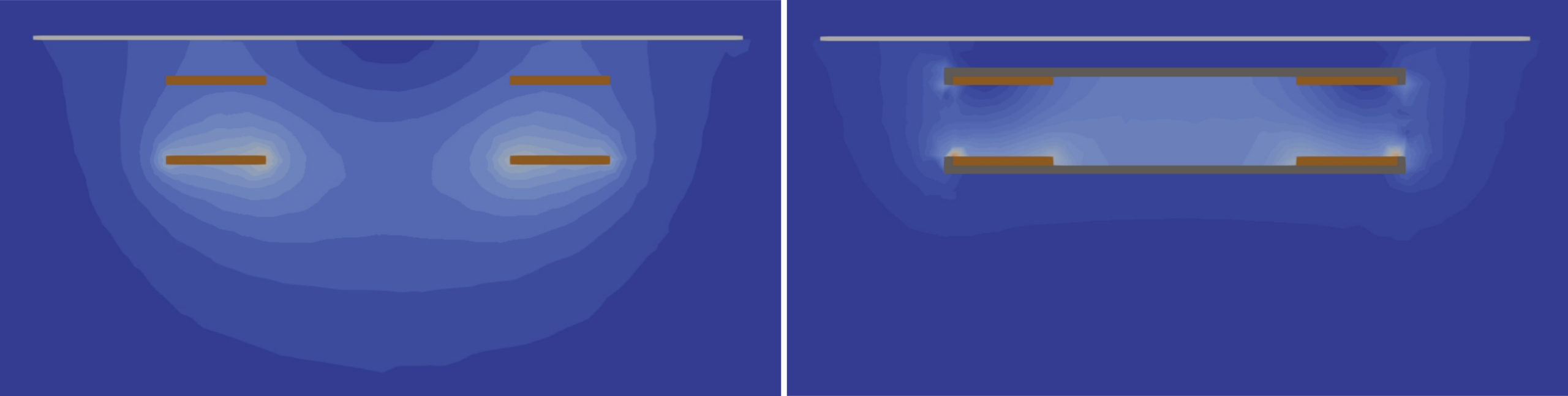
Image 2 – Open coil and backplate magnetic field without (left) and with (right) ferrite shielding.
Practical design fixes worth testing
There is no universal fix, because every WPT system has a unique size, operating frequency, and mix of materials. However, these practical steps are always worth testing during the design phase:
- Increase distance: Maximize the physical space between the active magnetic field and metal backplates.
- Add magnetic shielding: Place ferrite or nanocrystalline materials between the coils and the metal parts to safely guide the magnetic field away.
- Break up metal surfaces: Add physical slits or cuts to solid metal plates to stop large eddy currents from forming.
- Avoid closed metal loops: Do not use continuous metal rings, such as solid bezels or frames, around the Tx or Rx coils.
- Use plastic or polymer hardware: Swap out metal screws, brackets, and standoffs for non-conductive alternatives where possible.
- Test for misalignment: Always compare how the magnetic field behaves when the charger is perfectly centered versus when it is shifted off-center.
- Retune the circuit: Always adjust the tuning to match the final assembled product, because nearby metal will naturally change the system’s inductance.
- Check for metal heating: Verify the temperature inside the backplates and magnets, not just the copper coils.
The goal isn’t to remove all structural metal, which is rarely possible. The goal is to figure out which parts are harmless and which parts are quietly draining power.
Conclusion: treat mechanical parts as active components
Metal parts and alignment magnets do not automatically ruin wireless charging. In fact, magnets are often needed to help users align the device, and backplates provide necessary structural support.
The problem starts when these components are treated merely as passive mechanical details. If a metal part sits inside an alternating magnetic field, it becomes an active part of the electrical system. Left unchecked, these nearby structures will distort the magnetic field, create eddy currents, generate unwanted heat, change electrical parameters, and ultimately lower charging efficiency.
This is why reliable testing requires simulating the charger exactly as it will be built. By modeling the complete assembly in software—including the coils, ferrite, magnets, housing, circuit behavior, and physical misalignment—engineers can find and fix hidden losses before they ever show up in a physical prototype.