
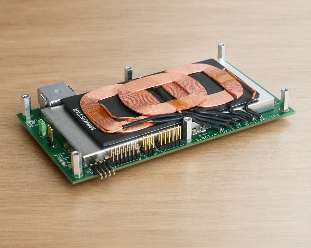
Wireless Charging coil design: efficiency, size, and heat
A coil can couple well, but run too hot.
It can fit nicely into the product, but lose efficiency.
It can handle misalignment, but require more space than the mechanical team wants to give.
That is the trade-off engineers keep running into:
- efficiency,
- package size,
- and heat.
You can improve one side of the triangle and still create a problem on another side. This is why coil design needs to be checked as a system, not as a drawing that looks fine on paper.
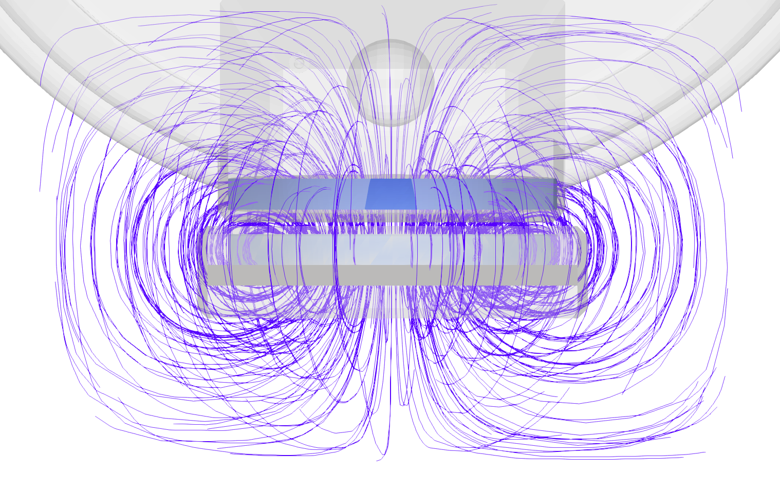
Image source: CENOS industrial robot wireless charging case study
Source link: Wireless charging of industrial robots: case study – CENOS : Simulation Software : Induction Heating : Radio Frequency : Wireless Charging
The trade-off triangle
In wireless charging, the coil that fits the product is not always the coil that gives the highest efficiency.
A larger coil can improve coupling, but the product may not have room for it.
More turns can increase inductance, but they can also increase resistance and heat.
A thinner PCB coil can help with packaging, but it often brings higher resistance and lower efficiency compared with wire-wound coils.
This is not only a CENOS observation. NXP’s application note on wireless charging coils makes the same practical point: coil construction must match the required power, working frequency, coil area, and thickness. It also notes that ferrite material and thickness influence maximum power transfer for a certain temperature rise. In other words, packaging and thermal behavior are part of the electrical design, whether we like it or not.
This is why simulation is useful early in design review. It lets engineers compare coil shape, size, turns, strand setup, ferrite placement, and alignment before ordering another prototype.
Field shape shows what the numbers alone can hide
The first thing to check is the magnetic field.
If the field is spread where it should not be, the system may waste energy. If the field is too concentrated in one area, the design may create local heating. If the field shifts too much with movement or misalignment, the product may perform well only in one narrow position.
In the industrial robot charging example, CENOS shows the magnetic field distribution around the transmitter and receiver coils. This helps engineers see where the field is concentrated and where coupling may be weaker.
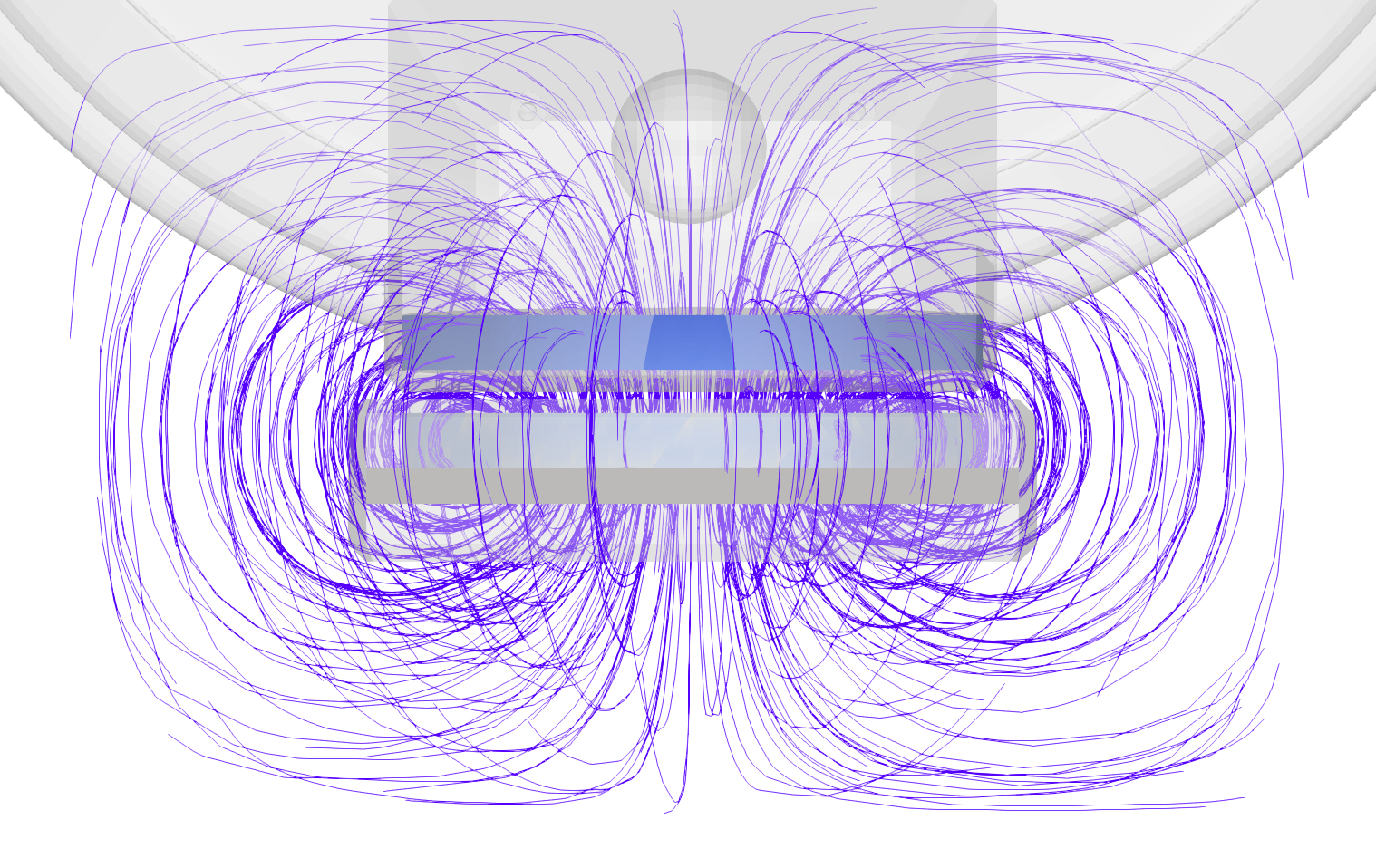
Image source: CENOS industrial robot wireless charging case study
Source link: Wireless charging of industrial robots: case study – CENOS : Simulation Software : Induction Heating : Radio Frequency : Wireless Charging
This kind of view is useful because wireless charging efficiency is not only a circuit result. It is a geometry result too.
Coil size, coil distance, coil shape, and ferrite coverage all affect how much useful field reaches the receiver.
Alignment tolerance is part of coil design
A coil can look efficient when perfectly aligned. That does not mean it will be efficient in field conditions.
Phones are placed slightly off-center.
Robots stop a few millimeters away from the target.
E-bikes and scooters lean, move, and park differently every time.
This is where field-line visualization becomes useful. It shows whether the energy path remains stable when the receiver is not placed perfectly.
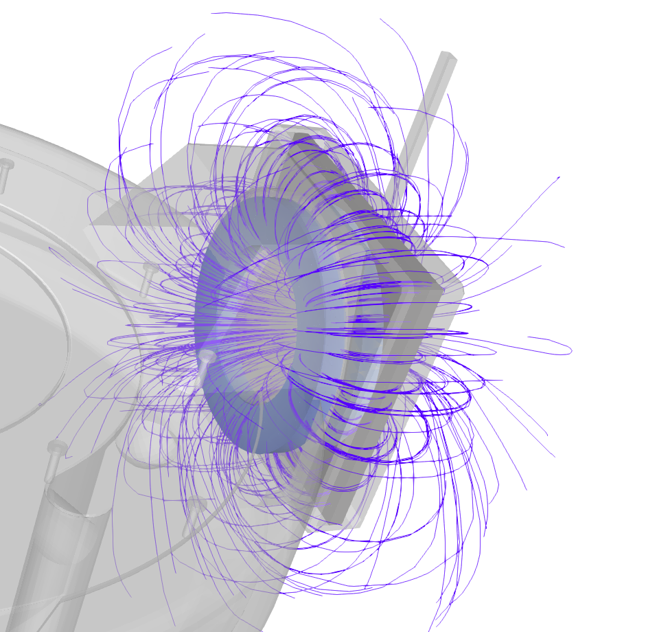
Image source: CENOS industrial robot wireless charging case study
Source link: Wireless charging of industrial robots: case study – CENOS : Simulation Software : Induction Heating : Radio Frequency : Wireless Charging
If field lines are well guided between the transmitter and receiver, the design has a better chance of keeping coupling stable. If field lines spread too widely, the system may lose efficiency and create unwanted losses in nearby materials.
This is especially important for industrial robots. They often need charging systems that work with repeatable docking, but not always perfect docking. Simulation lets engineers test those positions before hardware.
Heat is where the design trade-off becomes visible
Efficiency loss often ends up as heat.
A multicoil solution is used when the free positioning design is required. The transmitter checks each coil coupling to the receiver, and then selects the coil with the best coupling for the power transfer. It can energize one coil only or several coils together. The simultaneously energized coils can provide higher power transfer capability and larger freedom for the receiver coil placement.
The mobile phone case study is a good example.
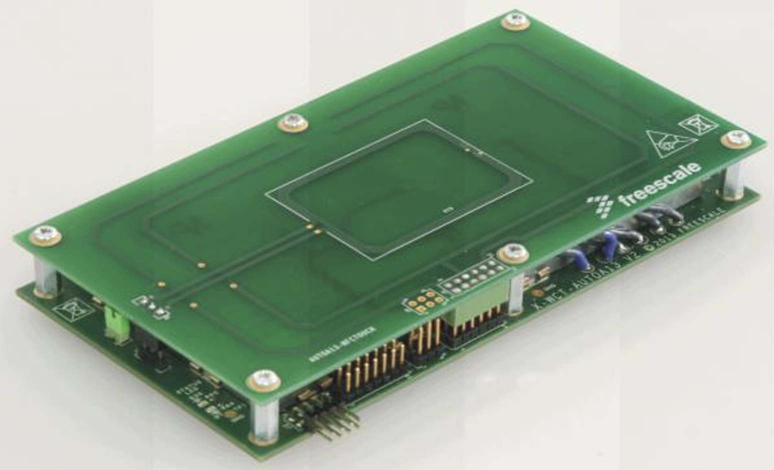
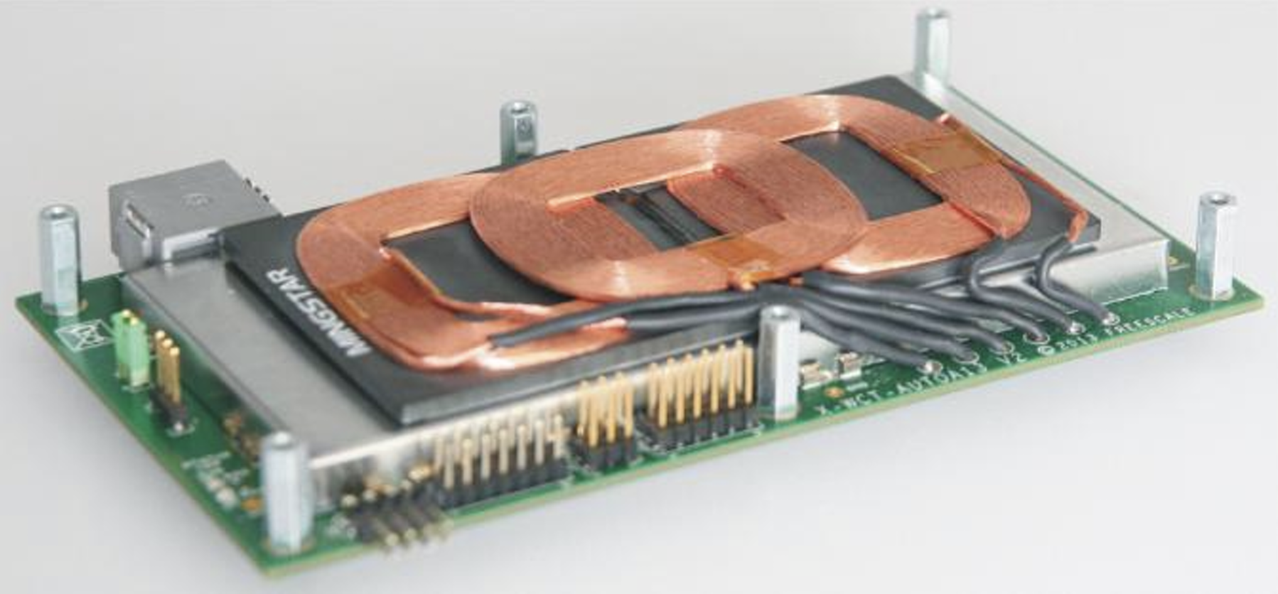
Image source: https://www.nxp.com/docs/en/application-note/AN4866.pdf
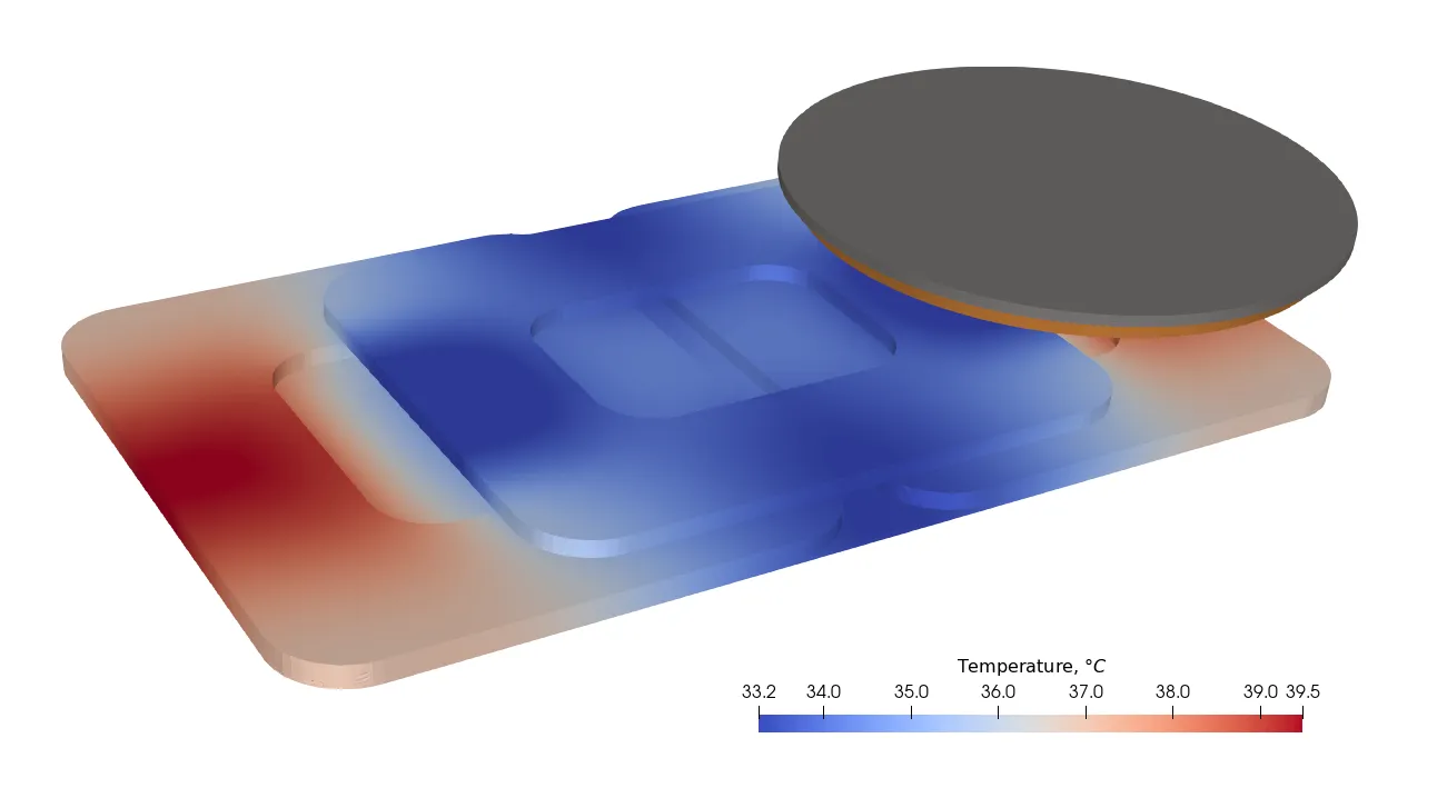
Image source: CENOS mobile phone wireless charging case study
Source link: Wireless charging simulation for mobile phones: case study – CENOS : Simulation Software : Induction Heating : Radio Frequency : Wireless Charging
The temperature map shows how coil placement and transmitter layout affect the heating pattern across the charging area.The important point is not only the maximum temperature. The temperature pattern matters too.
A local hot area may point to poor coil placement, poor alignment, poor shielding, or losses in nearby materials. A design that looks acceptable by coupling coefficient alone may still create thermal problems after repeated charging cycles.
This is why temperature maps should be reviewed together with magnetic field plots, coupling coefficient, resistance, Q factor, and active power. One result does not tell the full story.
The outside research says the same thing
A 2022 MDPI paper studied thermal behavior in coupled resonant coils for EV wireless charging. The researchers built a coil model, simulated electromagnetic and thermal behavior, and compared different material choices. Their model used a 60 mm coupling distance, and the selected copper coil reached a maximum temperature of about 74.98 °C after 30 minutes of operation.
Source link: Thermal Analysis of Coupled Resonant Coils for an Electric Vehicle Wireless Charging System
Before comparing efficiency or temperature results, engineers need to define the physical coil stack correctly. The coil does not work alone. Its behavior depends on coil diameter, number of turns, ferrite or magnetic core layers, protective layers, and the air gap between transmitter and receiver.
The figure below shows a basic wireless charging coil arrangement from the top view and side view. It helps explain why packaging decisions matter. A small change in coil size, ferrite coverage, or gap distance can change coupling, losses, and temperature rise.
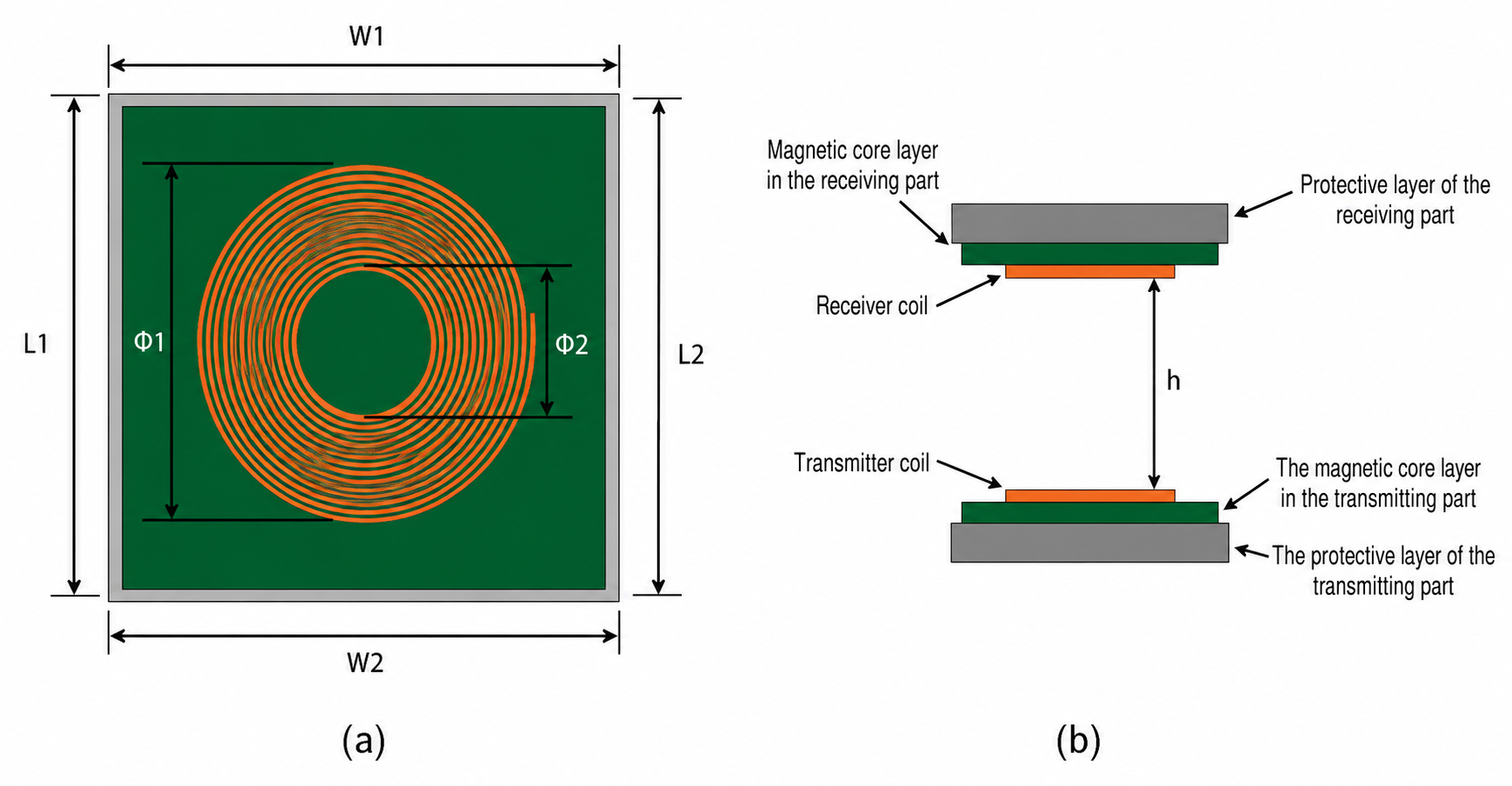
Image source: Basic wireless charging coil stack-up showing transmitter and receiver coils, magnetic core layers, protective layers, and the air gap between both sides.
Source link: Thermal Analysis of Coupled Resonant Coils for an Electric Vehicle Wireless Charging System
Coil geometry is only one part of the design. The real test starts when the receiver is not perfectly aligned with the transmitter.
The figure below shows how the magnetic flux changes when the receiving pad is shifted from the ideal position. As misalignment increases, the field becomes less evenly guided between the coils. That means weaker coupling, lower efficiency, and a higher chance that the system needs more current to deliver the same power.
This is why coil design should not be checked only at perfect alignment. A useful design review should include offset positions too, because the product will not always be placed exactly where the simulation model wants it to be.
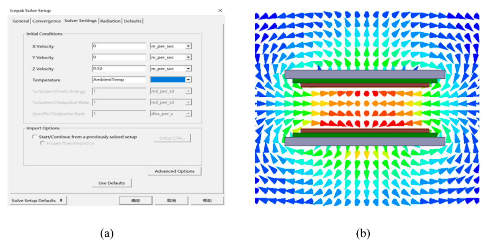
Source: Scientific Reports, 2024. Design and implementation of a high misalignment-tolerance wireless charger for an electric vehicle.
Source link: Thermal Analysis of Coupled Resonant Coils for an Electric Vehicle Wireless Charging System
This outside example supports the same point: coil design is not only about transferring energy. It is also about keeping the system within a practical temperature range.
For engineers, this means thermal analysis should not be added at the end. It should be part of coil design review from the start.
Coil type changes the compromise
CENOS WCH allows engineers to define different coil types and physical parameters, including number of turns, number of strands, circular or rectangular strand shape, and strand size.
That matters because different coil types solve different problems.
A wire-wound coil can support efficient energy transfer, but it needs thickness.
A PCB coil can fit into a thinner package, but it may increase resistance and reduce efficiency.
A multi-coil transmitter can improve placement flexibility, but it adds control complexity and may create new thermal questions.
Here is one visual from the mobile phone case showing magnetic field behavior around the charging setup.
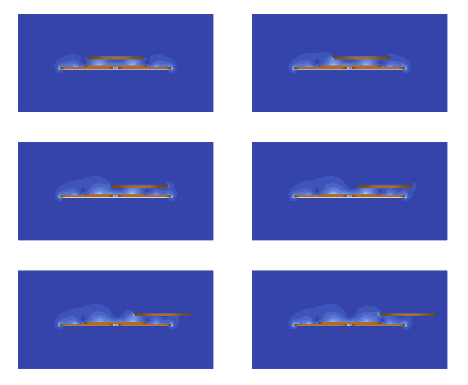
Image source: CENOS mobile phone wireless charging case study
Source link: Wireless charging simulation for mobile phones: case study – CENOS : Simulation Software : Induction Heating : Radio Frequency : Wireless Charging
This is where simulation gives practical direction. Engineers can compare several coil layouts and check how each design behaves under the same charging conditions.
Company named Tiler used CENOS for micro-mobility charging
For e-bikes and scooters, the receiver coil cannot always be placed in a large flat area. The product has limited space. The vehicle may not park perfectly. The charging point may be built into pavement, a stand, or a docking post.
Tiler is a good example from the CENOS wireless charging case library. Tiler uses the vehicle kickstand as the receiver and a pavement tile as the transmitter. That creates a hard coil design problem: the system needs high misalignment tolerance, not only good performance in one centered position.
According to the CENOS case story, Tiler achieved an average K of 0.5 and Q of 700+ over a displacement of three times the receiver size.

Image source: CENOS micro-mobility wireless charging case study
Source link: Using simulation software to improve micro mobility mechanics – CENOS : Simulation Software : Induction Heating : Radio Frequency : Wireless Charging
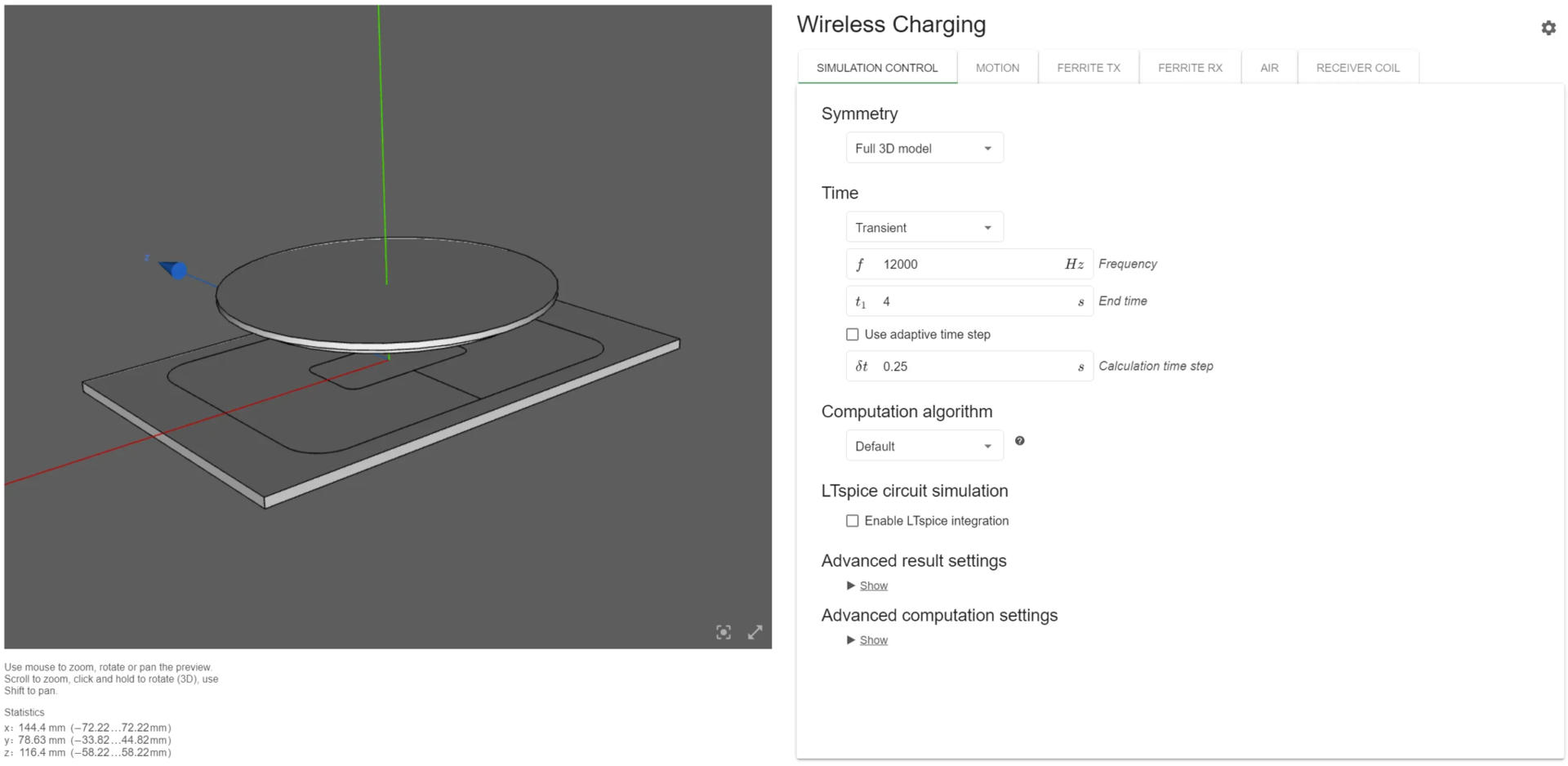
Image source: CENOS micro-mobility wireless charging case study
Source link: Using simulation software to improve micro mobility mechanics – CENOS : Simulation Software : Induction Heating : Radio Frequency : Wireless Charging
This is the kind of proof that matters. It is not about one ideal lab position. It is about designing a coil system that keeps working when the receiver position changes.
Performance graphs help decide whether the design is acceptable.
In the micro-mobility simulation, CENOS shows several performance plots, including Q factor, mutual inductance, stray losses, and coupling coefficient.
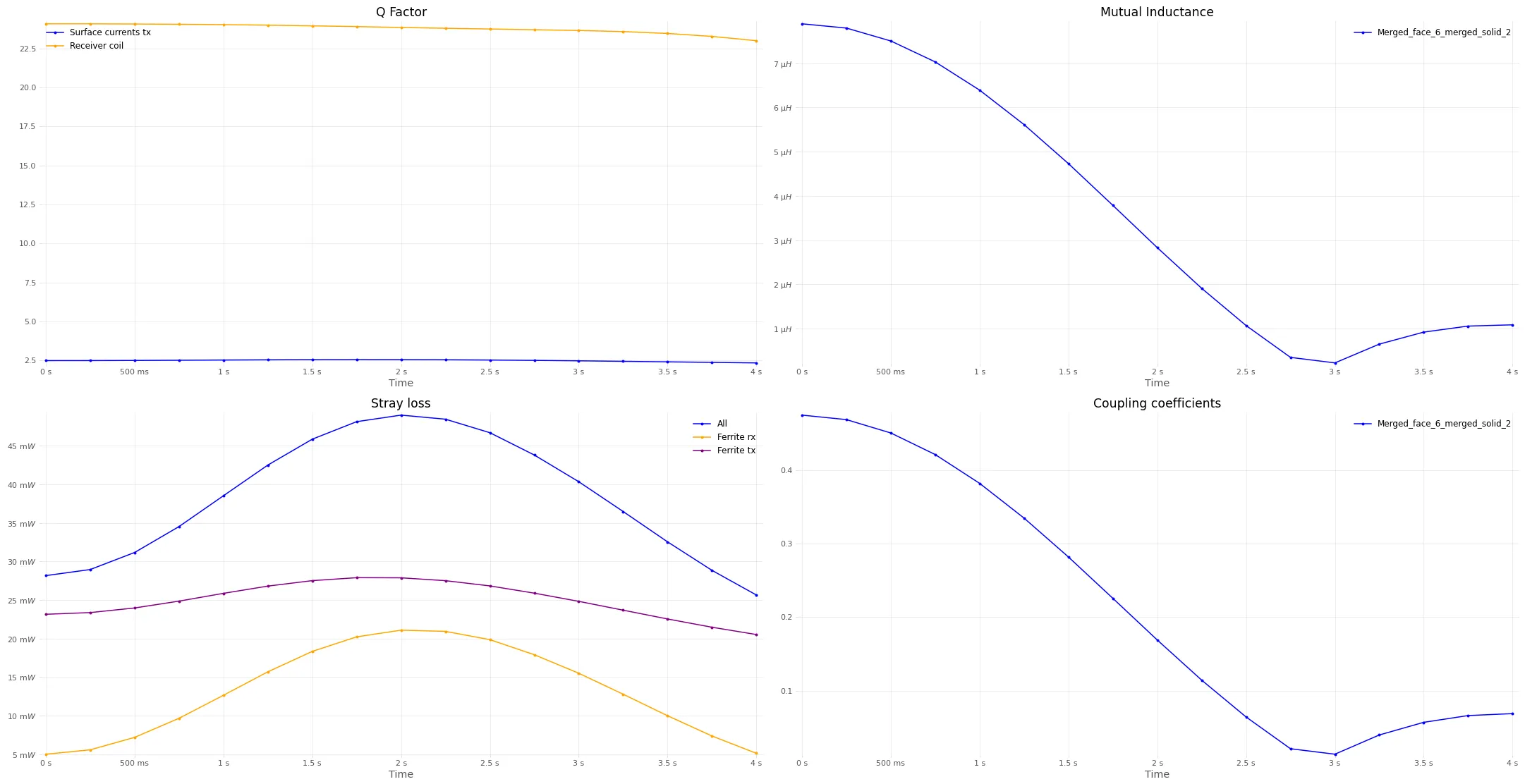
Image source: CENOS micro-mobility wireless charging case study
Source link: Using simulation software to improve micro mobility mechanics – CENOS : Simulation Software : Induction Heating : Radio Frequency : Wireless Charging
These plots help engineers answer practical questions:
- Is the coupling stable enough across movement?
- Does mutual inductance drop too far when the receiver shifts?
- Are losses growing in ferrite, copper, or nearby materials?
- Is the Q factor acceptable for the target design?
- Does the system still work within the available package size?
This is where the efficiency-size-heat triangle becomes measurable.
What to check before building the next prototype
Before building hardware, engineers should review five areas.
First, check placement. The coil may perform well in the center position, but the product may not be used that way. Test offset, tilt, air gap, and movement.
Second, check coil size. A larger coil may improve coupling, but it may not fit the product. A smaller coil may fit the housing, but it may need higher current or create more heat.
Third, check coil type. Wire-wound, PCB, single-coil, multi-coil, and double-D designs all create different compromises.
Fourth, check geometry simplification. CENOS can model stranded coils without resolving every strand in CAD, but the physical parameters still need to match the intended coil behavior.
Fifth, check the right results together. Magnetic field, temperature, Q factor, coupling coefficient, mutual inductance, resistance, active power, and stray losses should be reviewed as one design story.
The main point
Wireless charging coil design is a balancing act.
- The most efficient coil may not fit.
- The thinnest coil may not stay cool.
- The coil with great centered coupling may fail the alignment test.
- The design with better tolerance may need more space or different shielding.
Simulation helps engineers see those compromises before the prototype stage. Not because simulation replaces engineering judgment, but because it gives engineers more evidence before they spend time and money on hardware.
That is the practical goal: choose the coil design that fits the product, transfers energy efficiently, and stays within a safe thermal range.
Not one perfect coil.
The right compromise for the product.