Induction coil cooling design: How to prevent overheating and early tool failure
The part can heat correctly.
The hardening pattern can look fine.
The first test can pass.
And the coil can still be moving toward early failure.
That is the uncomfortable part of induction coil cooling. A coil is not only a copper shape that transfers energy into the workpiece. It is also a tool that has to survive current, frequency, radiation from the hot part, water cooling, geometry limits, and repeated production cycles.
If heat is not removed well enough, the coil starts to fail from the inside of the design. The first signs may be local overheating, damaged concentrators, cracked copper, unstable performance, leaks, or short coil life.
So the main question is not only:
Does the part reach the required temperature?
The better question is:
Can the coil keep doing that without overheating or failing too early?
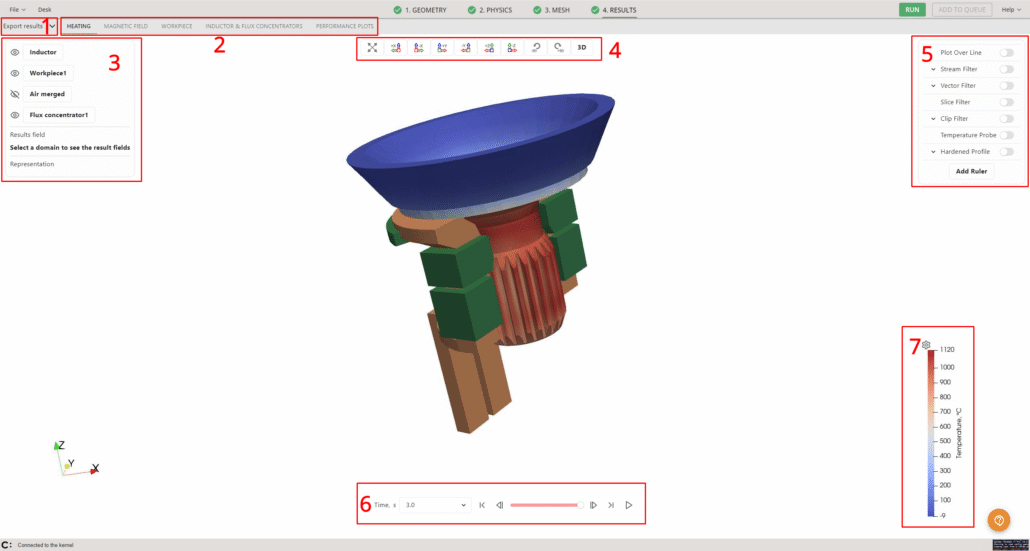
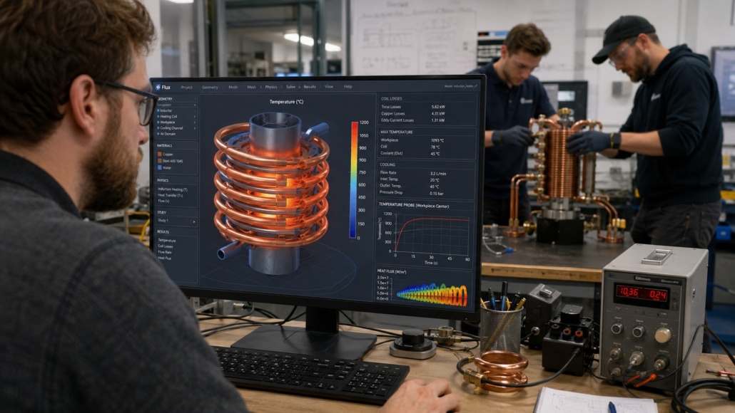
Figure 1. The part result matters, but the coil temperature must be checked as part of the same design.
Why coil cooling becomes a production problem
A coil can survive early tests and still fail too soon in production.
This happens because early testing often focuses on the part. Engineers check the heating pattern, case depth, cycle time, and surface temperature. That is normal. Those are the visible process results.
But the coil has its own thermal story.
A small hot spot in the coil may not stop one test. In production, that same hot spot is repeated thousands of times. Over time, it can lead to:
- copper overheating
- local softening
- cracking near sharp turns or joints
- damaged insulation
- faster concentrator degradation
- water leaks
- unstable electrical contact
- repeated maintenance stops
- shorter tool life
This is why coil cooling should not be treated as a secondary setting. It is part of the coil design.
What CENOS can check today
CENOS can help engineers analyze coil overheating risk by looking at electromagnetic loading, heat generation, wall thickness, cooling boundary conditions, temperature distribution, and local hot spots.
That is useful when the question is:
- Where does the coil become too hot?
- Which geometry creates the highest thermal load?
- How does wall thickness change coil temperature?
- How sensitive is the coil to current, frequency, and cooling assumptions?
- Is the hot spot close enough to the cooling channel?
- Does a design change reduce overheating risk?
CENOS Fluids tool brings in new capabilities. It would allow engineers to analyze cooling-liquid flow inside the inductor, not only approximate cooling with boundary conditions. That would add a much stronger layer to coil lifetime analysis.
The main causes of induction coil overheating
Induction coil overheating usually comes from a combination of design and process factors.
The most common ones are:
- the cooling channel is too far from the hottest region
- the copper wall is too thick in the wrong place
- the coil has sharp corners or tight sections with high current concentration
- the water flow is too weak for the thermal load
- the frequency shifts losses toward a sensitive region
- the current is increased without checking coil temperature
- the concentrator traps heat or receives insufficient cooling
- electrical contact creates local resistance heating
- the production cycle repeats heat faster than the coil can remove it
The dangerous part is that these issues do not always show up in the part first.
Sometimes the part is acceptable, but the coil is the weak point.
How to prevent overheating and early tool failure
The prevention method is straightforward:
Do not design the heating pattern first and check the coil later.
Check both together.
To reduce overheating risk:
- keep the cooling channel close enough to the expected hot zones
- avoid thick copper sections where heat has a long path to the cooling channel
- remove sharp turns where current and thermal stress can concentrate
- check whether concentrators are increasing local coil temperature
- compare several wall thickness options
- test the design at the planned current and frequency range
- check coil temperature over the full heating cycle, not only at one time step
- use probes and section cuts to measure gradients through the copper
- keep a safety margin for production variation
- use CFD when internal water flow is the unknown part of the design
This is not about making the coil look better in a screenshot.
It is about finding out whether the tool can survive production.
Variable 1: Cooling-channel position
Cooling-channel position is one of the first things to check.
If the hottest part of the coil is far from the cooling channel, heat has to travel through more copper before it can be removed. That can create a local temperature rise even when the average coil temperature looks acceptable.
A common problem is a corner, nose, or narrow section that receives high electromagnetic loading but sits too far from the water path.
In this case, the fix is not always higher water pressure. Sometimes the better answer is a different coil section, a better channel position, or a geometry change that reduces local loading.
How to prevent overheating here:
- place cooling channels close to the strongest thermal load
- avoid isolated copper regions with no good heat path
- check corners, noses, brazed areas, and concentrator zones
- compare the temperature before and after moving the channel
- do not rely only on average coil temperature
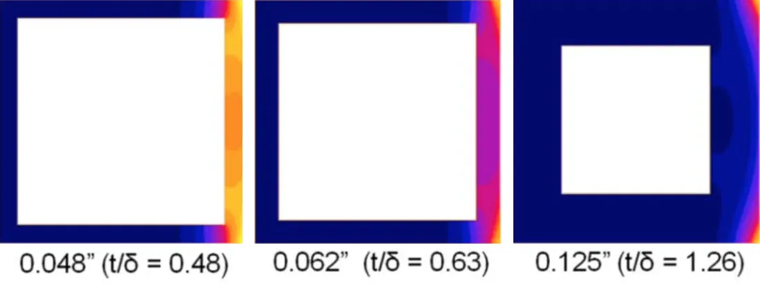
Figure 2. Cooling-channel distance can decide whether a hot region stays controlled or becomes a tool-life problem.
Variable 2: Wall thickness
Wall thickness changes the cooling behavior of the coil.
A thicker wall can sometimes help electrical behavior, depending on frequency and geometry. But a thicker wall also gives heat a longer path to the cooling channel.
That trade-off matters.
If the wall is too thin, the coil may have mechanical or manufacturing limits. If it is too thick, the hottest region may not cool fast enough. The right wall thickness is not chosen by habit. It should be checked against frequency, current, cooling strength, and the target tool life.
How to prevent overheating here:
- compare several wall thickness options
- check the hottest point, not the average
- inspect temperature gradients through the copper wall
- avoid thick sections near high-loss regions
- choose wall thickness together with frequency and current settings
- check whether the coil reaches a stable thermal window during the cycle
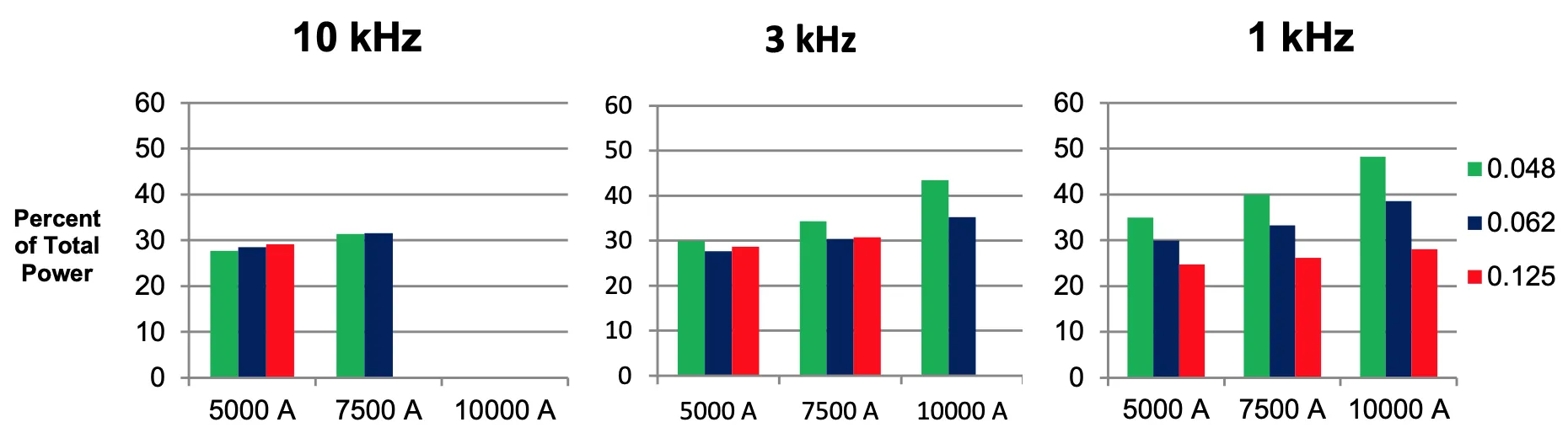
Figure 3. Wall thickness affects both electrical behavior and cooling response.
Variable 3: Current
Current does not only heat the part.
It also increases the thermal load on the coil.
When current increases, weak coil-cooling decisions become more visible. A design that survives at one current level may run too hot after a production adjustment.
This is why coil cooling should be checked across the expected process range, not only at the nominal setting.
How to prevent overheating here:
- test the coil at planned minimum and maximum current
- check whether the hot spot moves when current changes
- inspect local current density in sharp regions
- add margin for process tuning during production
- avoid designs where a small current increase creates a large coil-temperature jump
Variable 4: Frequency
Frequency changes where losses appear.
A coil that works at one frequency may behave differently at another. The heating depth in the part changes, but the coil loading also changes.
That is why frequency should not be checked only from the part side. It should also be checked from the coil-temperature side.
How to prevent overheating here:
- compare coil temperature at each planned frequency
- check whether losses concentrate near thin or poorly cooled sections
- inspect concentrator regions
- compare field view and thermal view together
- avoid selecting frequency only by required case depth
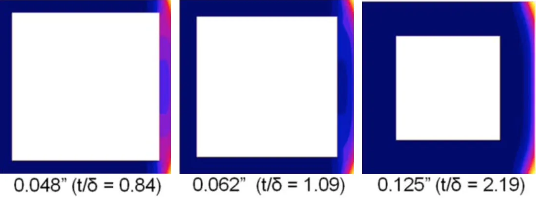
Figure 4. Frequency changes both part heating and coil thermal load.
Variable 5: Cooling strength
Cooling in CENOS is usually represented through heat transfer boundary conditions. This is useful for comparing designs, but it is still an approximation.
That means the result depends on the cooling assumptions.
If the heat transfer coefficient is too optimistic, the simulation may understate overheating risk. If it is too conservative, the design may look worse than it is. The right way is to use realistic values, compare scenarios, and validate with measurements where possible.
How to prevent overheating here:
- run conservative and optimistic cooling cases
- check how much the coil temperature changes
- avoid designs that only work under ideal cooling assumptions
- measure water temperature, flow, and pressure during testing
- use CFD when flow distribution inside the coil is important
- plan for the Fluids tool when internal cooling-flow behavior needs to be analyzed directly
What engineers should look at in the results
A thermal image is not enough.
The image shows where the coil is hot. It does not fully explain why.
To understand the result, combine several views.
1. Start with the magnetic field
If a coil section is overheating, first check the electromagnetic field.
Dense field regions, sharp turns, narrow gaps, and concentrator edges can explain why heat appears in one local area.
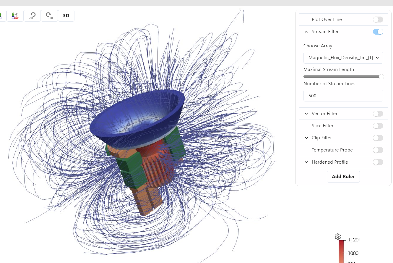
Figure 5. Magnetic field streamlines. A thermal problem often starts as an electromagnetic loading problem.
2. Check coil temperature
Find the hottest point in the coil.
Do not only check the maximum value. Check where it appears. A hot spot near a joint, corner, concentrator, or thin wall is more concerning than a warmer region in a safer part of the coil.
3. Cut through the geometry
Surface views can hide the problem.
Use section cuts to inspect what happens inside the copper wall. The key question is whether heat has a reasonable path to the cooling channel.
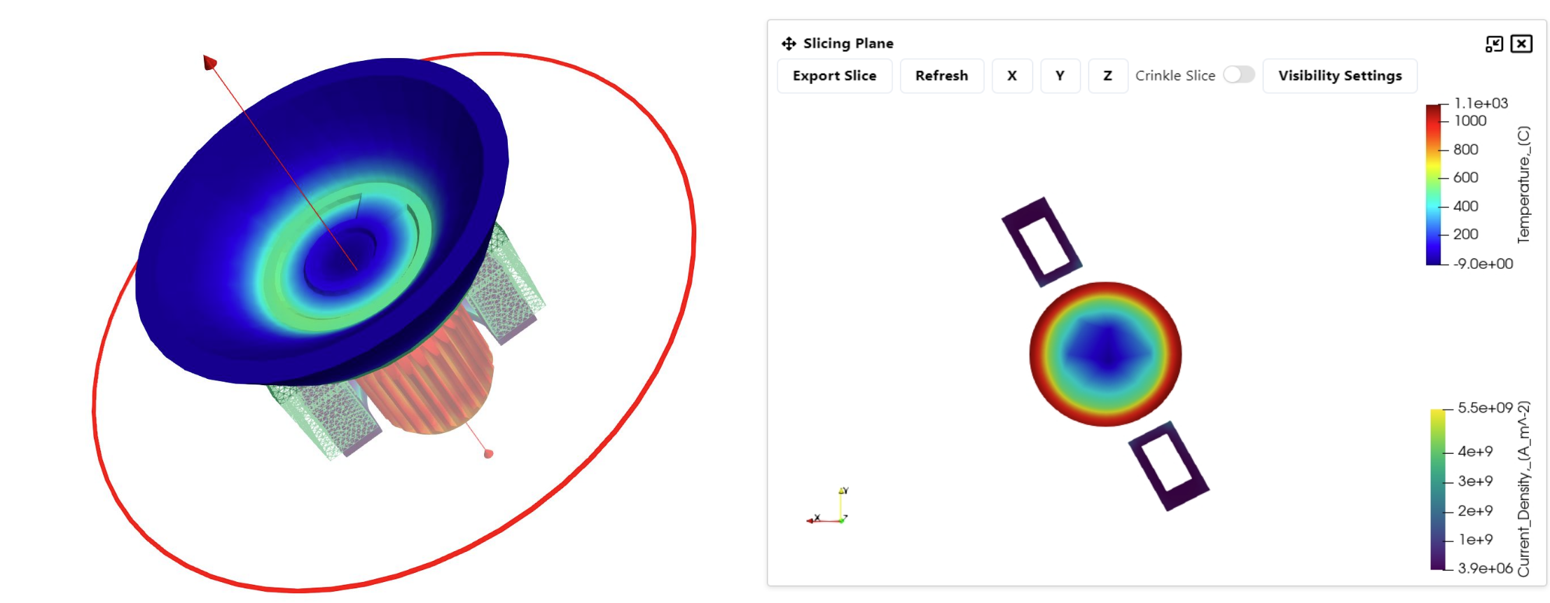
Figure 6. Slice view for internal result inspection. Section cuts help show whether heat is trapped inside the coil wall.
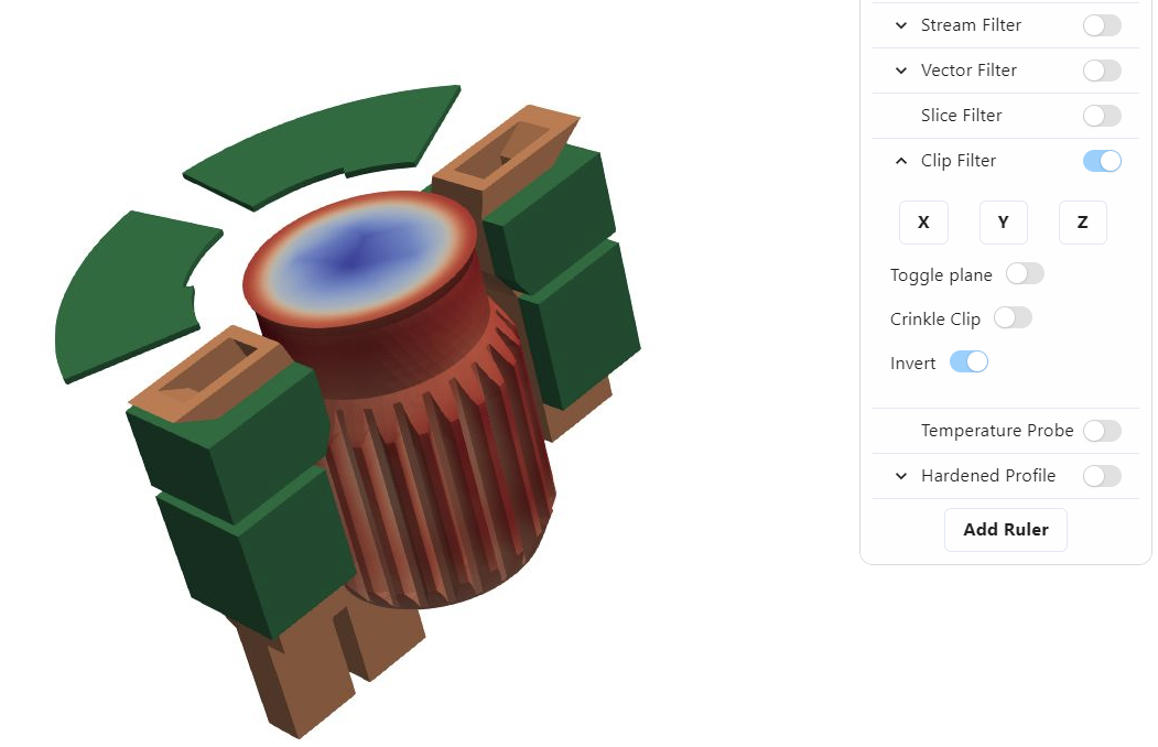
Figure 7. Clip view for exposing hidden hot regions. Hidden geometry can carry the critical coil temperature.
4. Measure the temperature gradient
A steep temperature gradient can point to thermal-stress risk.
CENOS does not replace structural thermal-stress analysis, but a steep gradient is still a warning sign. It tells the engineer that one region is carrying too much thermal load.
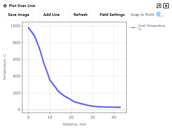
Figure 8. Plot-over-line result. Local gradients explain more than a color map alone.
5. Check time behavior
A coil may look acceptable at one moment and still keep heating over time.
Use probes or time plots to check whether the coil temperature stabilizes. If the temperature keeps rising, the design needs more work.
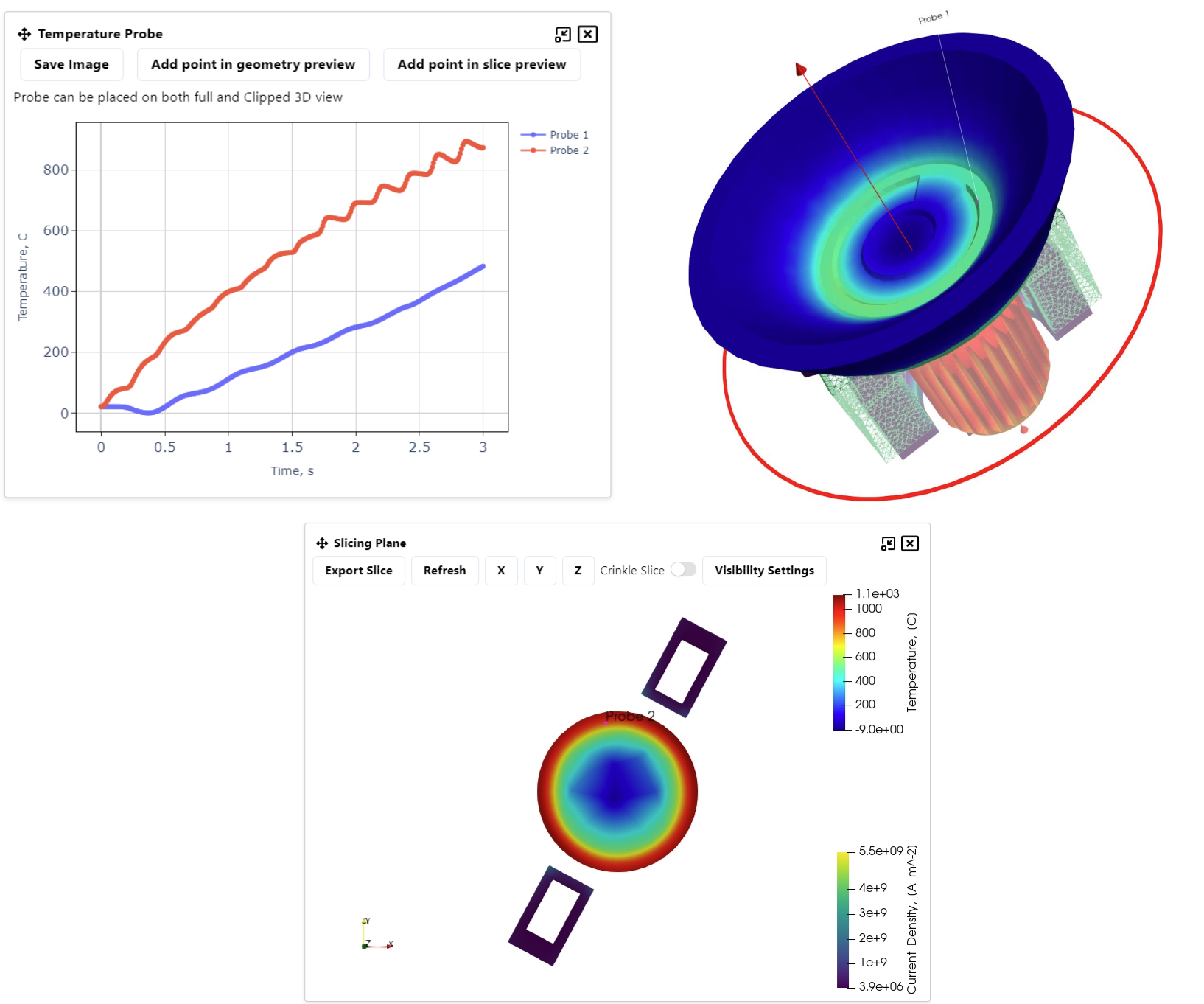
Figure 9. Local probes help show whether the coil is stabilizing or slowly moving toward overheating.
6. Check process stability
The last step is to inspect performance plots. A coil can survive one good-looking frame and still behave poorly over time. Power, current, voltage, and inductance plots help show whether the process settles.
How this prevents overheating:
- look for signals that stabilize after heat-up
- watch for drift that suggests changing coupling or thermal state
- use performance plots together with coil-temperature probes
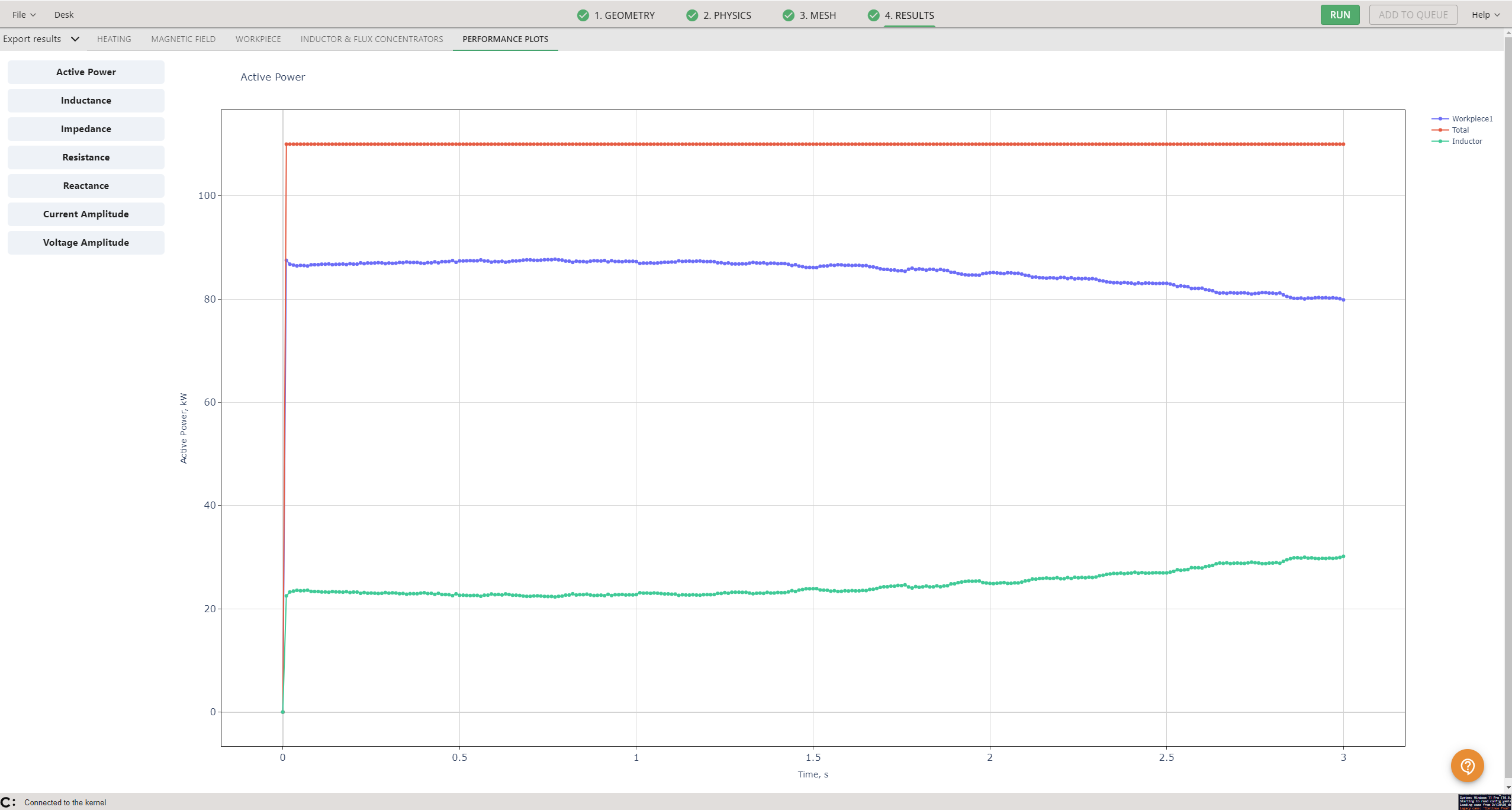
Figure 10. Active power plot. Performance plots help show whether the process settles or keeps drifting.
Client experience: coil life is not a theoretical issue
This is not only a design-theory problem.
In the GKN Driveline Celaya case, the team was dealing with high scrap rates and short coil life on a CV joint hardening line. The coils were failing after about 20,000 shots, causing downtime and maintenance.
By using simulation to support process decisions and coil redesign, the team increased coil life to more than 122,000 shots. The same work also helped reduce scrap and improve line performance.
The important lesson is not that every case will produce the same number.
The lesson is this:
Coil life improves when engineers stop treating the coil as a fixed object and start treating it as part of the process design.
That means checking:
- the hardening result
- the coil temperature
- the field distribution
- the concentrator position
- the sensitivity to gap and process settings
- the local overheating risk
When those are checked together, the coil has a better chance of surviving production.
Figure 11. In production, coil lifetime can matter as much as the heating pattern itself.
A practical checklist before releasing the coil
Before releasing an induction coil to production, check these points.
Coil overheating checklist
- What is the peak coil temperature?
- Where exactly is the hot spot?
- Is the hot spot close to a cooling channel?
- Is the hot spot near a joint, corner, or concentrator?
- How steep is the temperature gradient through the copper wall?
- Does the coil temperature stabilize during the cycle?
- What happens if current increases?
- What happens if frequency changes?
- What happens if cooling strength is lower than expected?
- Is the cooling-flow assumption realistic?
- Is CFD needed to check internal liquid flow?
- Is structural thermal-stress analysis needed for lifetime prediction?
- Has the design been validated with measured coil or water-temperature data?
What changes with CENOS Fluids
Today, CENOS can help engineers compare coil thermal behavior using cooling assumptions. That is already useful for identifying overheating risk.
With Fluids, the analysis moves closer to the cooling system itself.
That would help answer questions such as:
- Does the cooling liquid reach all important regions?
- Are there weak-flow zones inside the inductor?
- Is the channel layout creating pressure loss?
- Are some branches receiving more flow than others?
- Does the internal cooling design match the thermal load?
That turns coil cooling from a boundary-condition assumption into a deeper design question.
Conclusion
So, how do you prevent induction coil overheating and early tool failure?
By checking the coil as carefully as the part.
A good induction heating result is not enough if the coil runs too hot. The design has to meet the part requirement and stay inside a safe thermal window.
The practical method is:
- check the field
- check the coil temperature
- inspect the cooling-channel distance
- compare wall thickness options
- test current and frequency sensitivity
- measure local temperature gradients
- check whether the coil stabilizes over time
- validate the assumptions with production data
- use CFD when internal cooling flow is the main unknown
CENOS can help engineers find overheating risk before the tool reaches production. That already saves time, tests, and maintenance pain.
Preventing early tool failure starts with designing the heating process and the coil cooling together, not treating cooling as an afterthought.
