Closed coils simulations
CENOS Induction Heating software allows not only open, but also closed coils simulations. In this article you can find out about how to set up such simulations.
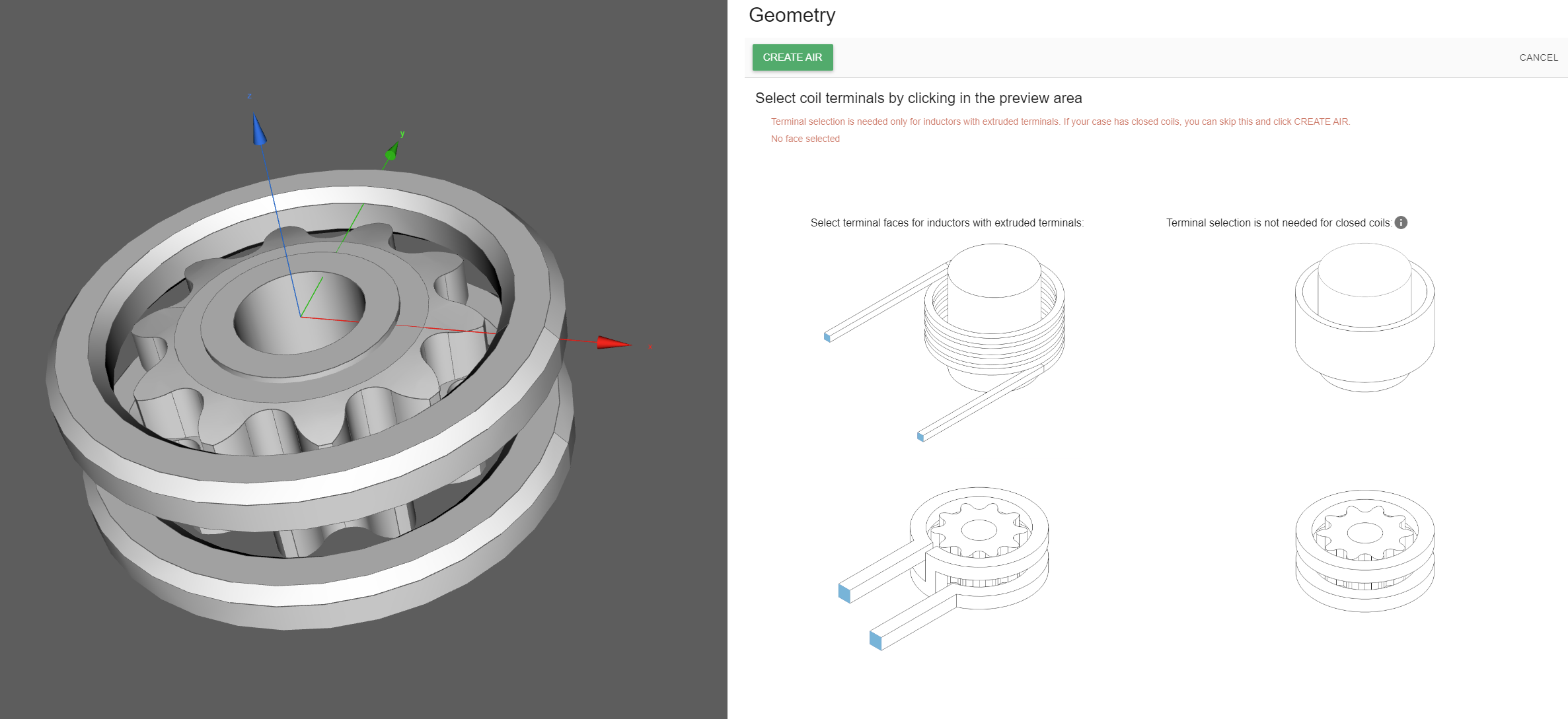
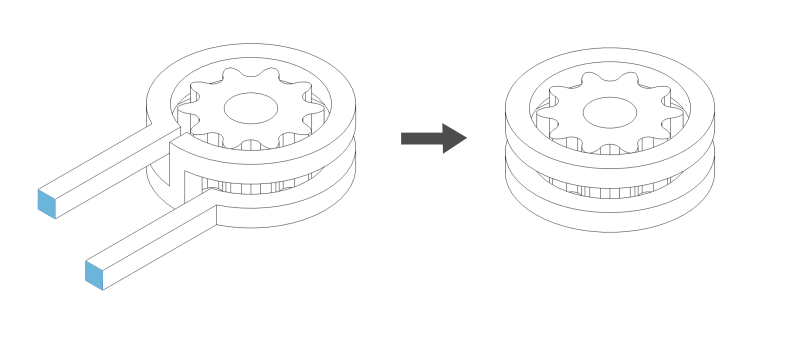
Air domain
Once you have uploaded your geometry, the air domain needs to be generated. For closed coils simulations, there is not need for terminal selection, as they are not extruded, so here you just click CREATE AIR without selecting anything else.
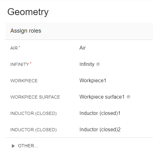
Inductor role
In the geometry roles window, you will see that you need to define the workpiece, workpiece surface and inductor (closed).
If you need to create an extra Inductor (closed) role, go to the Other… section and you will find this role in the dropdown menu.
Closed coil inductor physics
In the INDUCTOR tab you define the inductor properties.
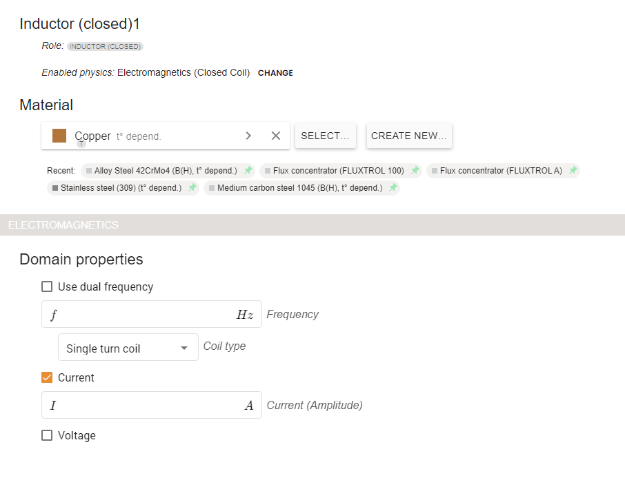
In this case, the inductor is defined as a closed coil and the material Copper is assigned automatically.
You need to specify the frequency for the inductor.
Next, you need to select if the inductor is a single turn coil or a multi-turn coil.
Single turn vs multi-turn coils
A single turn coil is one where each inductor winding is represented by a closed loop in the closed coil – it will also have the skin layers generated in the meshing section.
For single turn coil you also need to specify the current or voltage of the coil.
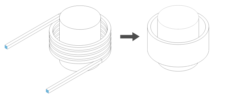
A multi-turn coil refers to a coil consisting of many fine turns of conducting wires. It can be created as a single solid from the CAD perspective, then you can assign the necessary values so that CENOS knows it is a multi-turn coil.
For multi-turn coil you also need to specify the current or voltage of the coil.
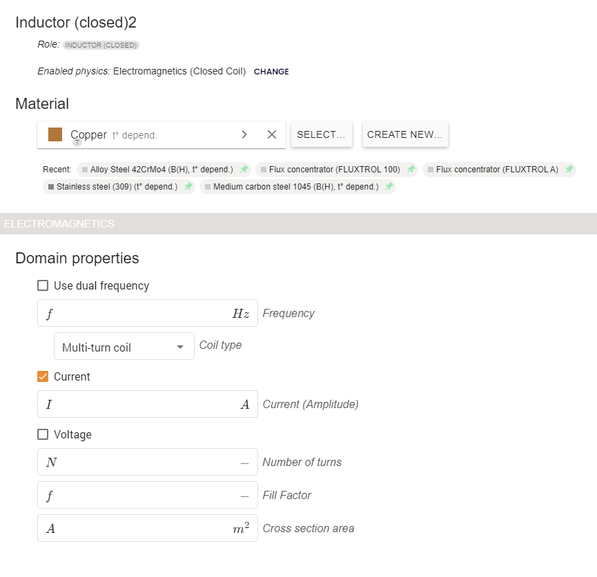
After that, you need to define the number of turns, fill factor and cross section area.
Fill Factor/Cross section area
The Fill Factor defines the proportion of the solid inductor area that is occupied by windings.
The Cross-Sectional Area represents the total area occupied by the solid inductor.
Example:
If you define a 10×10 mm square as the Closed coil cross section with:
- 1 winding (represented by the blue area), and
- winding radius of 5 mm,
the fill Factor and Cross-Sectional Area (represented by the green area) can be calculated as follows:

The Fill factor can be calculated for one winding – the same proportion will apply to the full solid inductor.
The Cross-Sectional Area in this case would be 100mm if there is only one winding, 200mm if there are two, 300mm if there are three windings and so on.
You can read more about stranded coils in our documentation article.
Then you can click RUN to start the simulation.
