Wireless charging simulation for mobile phones: case study
In this case study, we will examine the charging of electronic devices. Since mobile phone technology and wireless charging are the most recognizable topics, we will simulate the charging of a mobile phone.
What is the challenge?
In today’s world of consumer electronics, wireless charging for mobile phones has become an expected feature, providing users with convenient, cord-free power. However, developing efficient and reliable wireless charging solutions presents different challenges for engineers.
Different Qi standards, ranging from the low-power Basic Power Profile (BPP) to the higher-power Extended Power Profile (EPP), must be adhered to in order to meet diverse device requirements. The focus is mainly on compatibility, reducing heat generation, and maintaining energy transfer efficiency.
Engineers face the task of designing charging coils and optimizing placements to avoid energy losses and overheating, which can significantly impact user experience and device longevity.
What is the solution?
Using simulation software, engineers can visualize and test the effectiveness of wireless charging designs before creating physical prototypes. The following images from CENOS wireless charging simulation software demonstrate the factors in wireless charging development.
Temperature distribution in wireless charging:
This temperature distribution image visualizes how heat is dispersed across the charging area of a mobile device during wireless charging. The colors range from blue (cooler areas) to red (warmer areas), indicating temperature levels from 33.2°C to 39.5°C.
Generally speaking, temperature distribution can be influenced by the relative position of Tx vs Rx assemblies. Here temperature distribution is more affected by the relative position between Tx coils.
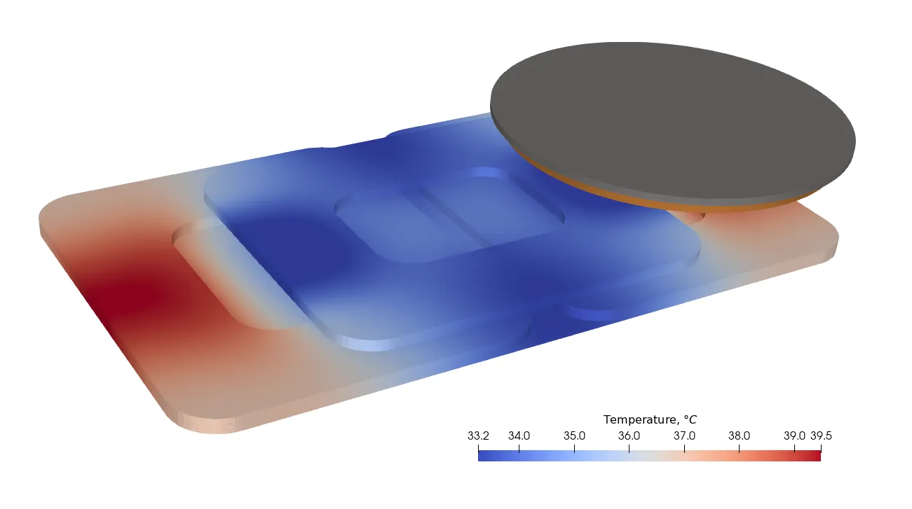
Temperature distribution comes from how the Tx coils are placed. This misalignment can lead to different problems:
- Reduced charging efficiency: Misalignment decreases the coupling between the coils, which results in less efficient energy transfer. This means more energy is wasted as heat rather than being effectively transferred to charge the device.
- Localized overheating: Certain areas of the device can become hotter due to inefficient energy transfer, potentially causing long-term damage to the battery or the device’s internal components.
- Longer charging time: Reduced efficiency means that the device will take longer to charge to full capacity, meaning an inconvenient user experience.
Magnetic field simulation in wireless charging:
The magnetic field simulation animation displays how the magnetic lines of force travel between the transmitter (charger) and receiver (phone) coils. These magnetic lines indicate the path through which energy is transferred wirelessly.

In an ideal setup, the magnetic field lines are well-aligned, maximizing energy transfer. However, if the phone and charger are misaligned, these problems may occur:
- Inefficient magnetic coupling: Misalignment disrupts the ideal flow of magnetic lines between the coils, and causes reduced magnetic coupling. This inefficiency means that only a fraction of the generated magnetic field effectively contributes to charging, while the rest dissipates as energy loss.
- Stray magnetic fields: Misalignment can cause magnetic fields to stray, potentially interfering with nearby electronic devices or components within the phone, which may affect device performance or safety.
Charger with magnetic field overlay:
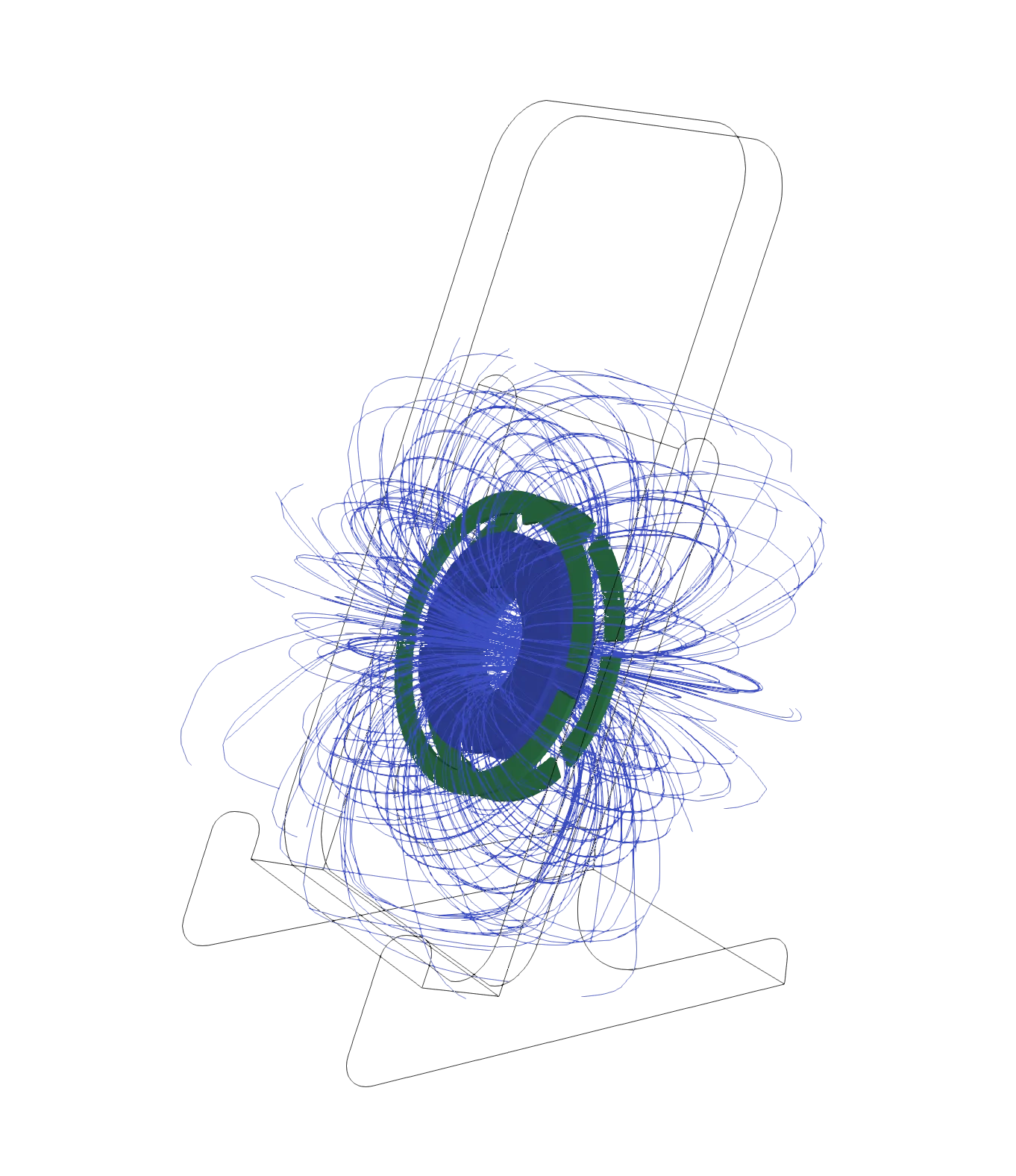
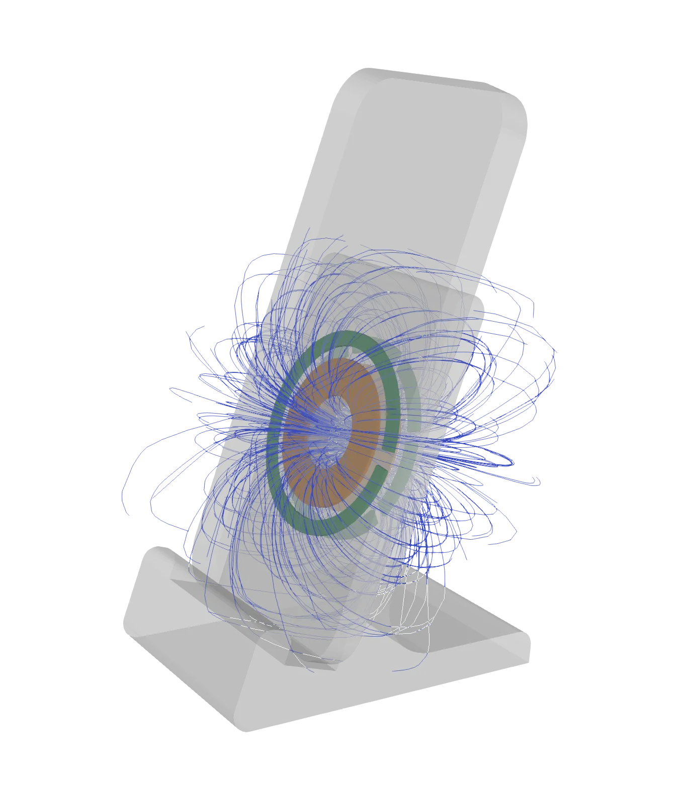
These two images illustrate a side view of the mobile device and charger setup with magnets. Using magnets improves the alignment of the coil. The magnetic field overlay shows how the magnetic lines circulate around the coils, showing the reach and strength of the field.
Engineers can use this data to refine the alignment and structure of the coils, ensuring optimal energy flow and reducing stray magnetic fields that could interfere with nearby electronics.
What is the result?
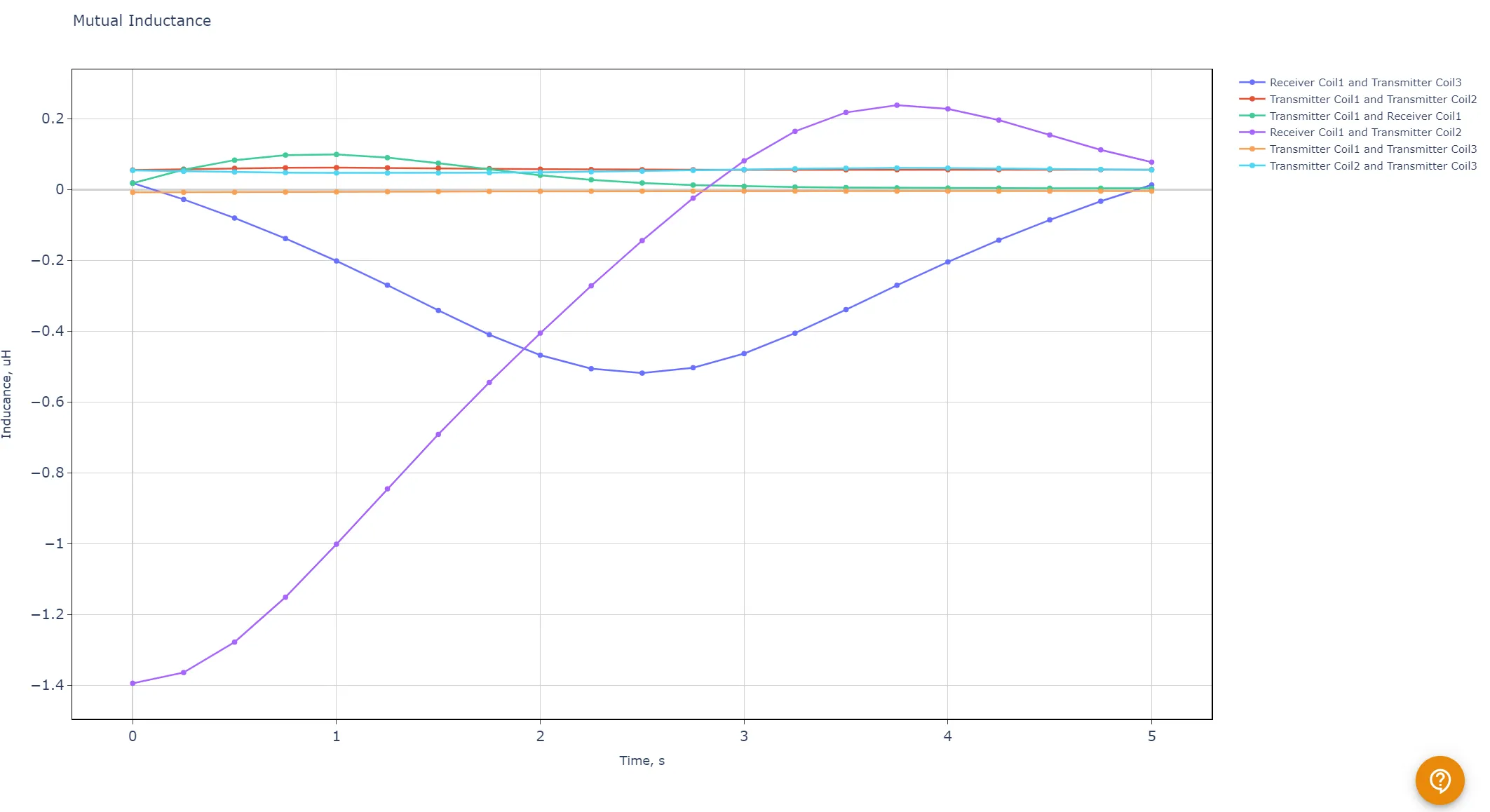
The simulation results are analyzed through coupling coefficient and mutual inductance graphs:
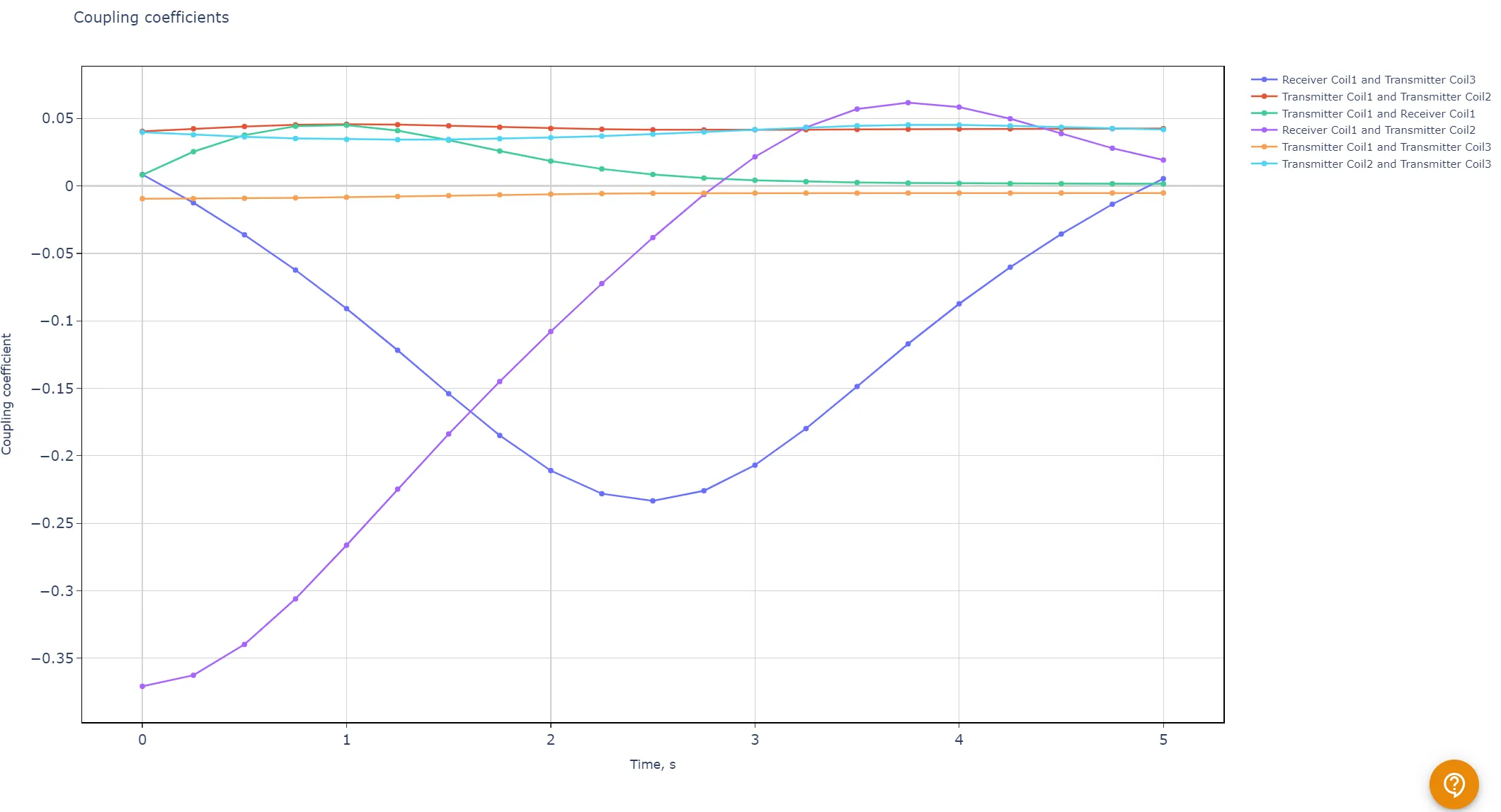
- Coupling coefficient graph: This graph shows how well the transmitter and receiver coils are coupled over time. High coupling coefficients indicate effective energy transfer, while lower values suggest misalignment or inefficiencies. Adjusting coil geometry based on this data allows engineers to maximize charging efficiency.
- Mutual inductance graph: This graph provides information about the mutual inductance between coils. A stable mutual inductance value shows a consistent energy transfer rate. Engineers can use these insights to improve coil positioning and the charging distance, achieving a stable and efficient wireless charging experience.
How Qi2 sets a new standard in wireless charging technology
The Qi2 wireless charging standard is an important leap forward in the world of wireless charging, bringing many limitations to previous Qi standards.
Here’s how Qi2 redefines the standard:
- Magnetic power profile (MPP): Qi2 has a new feature that improves alignment between the charging coil in the device and the charging pad. With precise magnetic alignment, energy transfer becomes significantly more efficient, reducing power loss and decreasing heat generation. This improvement will make mobile devices charge faster and avoid the risk of overheating which is a common issue in earlier wireless charging solutions.
- Improved energy efficiency: Energy efficiency is an important aspect of wireless charging, especially as more electronic devices are designed to rely on this technology. Qi2 optimizes energy transfer to reduce losses during charging, leading to lower energy consumption and more eco-friendly charging practices.
- Better user experience: The Qi2 standard’s improved alignment and power management features make charging more intuitive for users. With magnets, there is a better alignment, and users can simply place their device on a Qi2-compatible charger without worrying about positioning or orientation.
Wireless charging simulations help engineers design optimized charging systems without the need for repeated physical testing, saving time and resources. By understanding thermal profiles, magnetic field dynamics, coupling coefficients, and mutual inductance, engineers can create wireless chargers that deliver reliable, efficient, and safe charging experiences for end users.


