Wireless charging of electric vehicles: use case
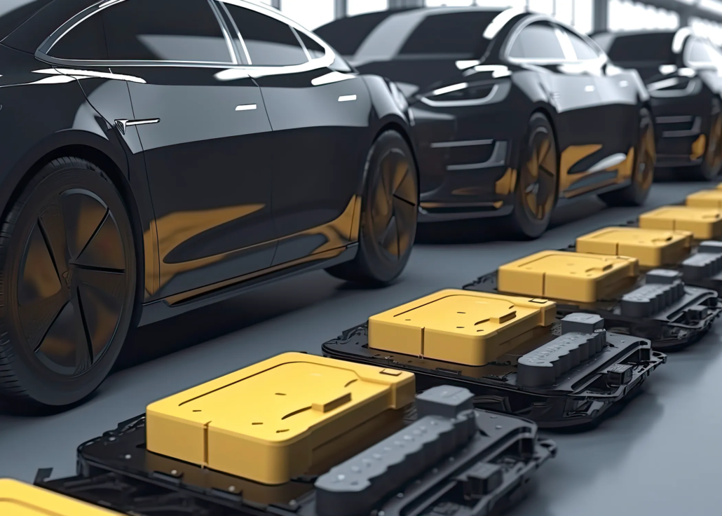
In the world of electric vehicles (EVs), charging speed and convenience are two of the most frequent questions that both manufacturers and drivers face today. The current methods of charging are often stationary, and time-consuming, creating barriers to widespread EV adoption. But what if there was a solution where your car could charge while driving? Imagine roads embedded with wireless charging technology, eliminating the need to stop for a charge.
One of the most exciting breakthroughs in this space involves wireless charging through electromagnetic induction. It’s not just about plugging in your vehicle anymore—companies are exploring how to charge EVs while they’re both parked and in motion. This opens up a future where charging could become as seamless as driving itself.
Stationary charging is simple but presents its own set of complexities. Some companies have already created solutions where a robot moves to the car’s parking spot, places the charger beneath the vehicle, and initiates charging. This method reduces the need for complex, expensive infrastructure, like embedding coils into roads.
Another interesting approach involves turning the entire parking lot into a wireless charging station. But even here, coil design (but also the whole transmitter-receiver system) is important to support the system’s work efficiently while respecting regulations, like limiting magnetic frequency to protect people.
What Is the Challenge?
Let’s look at the specific challenges posed by wireless charging for moving vehicles. When you’re driving, the position of the car is constantly changing. Receiver coils embedded under the car and coils placed under the road need to stay aligned for effective power transmission. The uneven road surfaces, car movement, and varying distances between the car and the coils make this a significant engineering challenge. One of CENOS’s customers is actively working on this type of solution, designing coils that can charge EVs as they drive.
Sweden has already begun testing a road that incorporates this technology, making it one of the first of its kind. However, achieving efficient energy distribution remains a key challenge. Engineers must develop systems that can adapt to the variable positioning and distance between the charging infrastructure and the car’s receiver coil.
Wireless charging technology for electric vehicles faces several major challenges, especially concerning energy transfer efficiency and thermal management. The basic principle behind wireless charging is electromagnetic induction between two coils: a transmitter coil embedded in the ground and a receiver coil installed in the vehicle. However, real-world conditions complicate this process.
Key challenges include:
- Coil alignment: The efficiency of energy transfer depends on how well the transmitter and receiver coils are aligned. Misalignment, whether due to vehicle positioning or uneven road surfaces, can significantly reduce the amount of energy transferred.
- Thermal management: Poor energy transfer can lead to excess heat generation, which not only reduces efficiency but can also damage the vehicle’s components and battery over time.
- Energy losses: Stray energy losses and low-quality energy transfer mechanisms, such as low inductance or poor coupling coefficients, can make the wireless charging system inefficient and uneconomical.
- Dynamic charging: For vehicles charging on the move, dynamic misalignment caused by motion poses an even greater challenge, as the coil positions constantly shift.
Given these challenges, engineers need reliable simulation tools to design, test, and optimize wireless charging systems that meet the demands of both stationary and dynamic EV charging scenarios.
Here is the simulation setup:
With CENOS Wireless Charging simulation software we set key parameters in designing and testing wireless charging systems, including motion-induced misalignment and coil design considerations such as turns, strands, and current.
The ability to simulate motion and thermal effects provides engineers with critical insights for optimizing both stationary and dynamic charging systems.
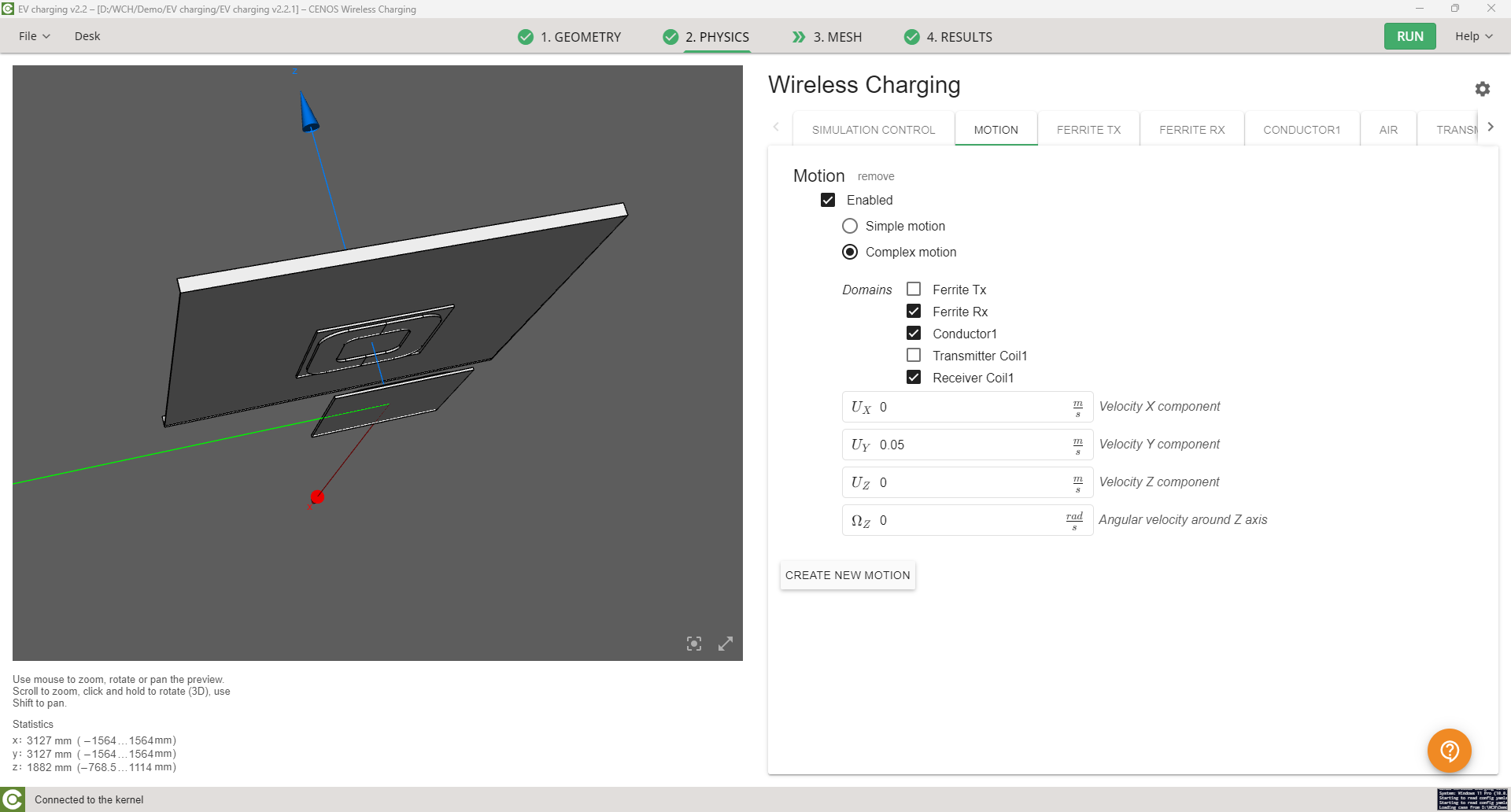
Motion settings for wireless charging simulation:
- Motion enabled: The simulation allows for the inclusion of motion to model how the receiver and transmitter coils interact while the vehicle is in motion.
- Domains: The user has selected specific domains to focus on, including the receiver ferrite (Ferrite Rx), transmitter (Transmitter Coil1), conductor (Conductor1), and receiver coil (Receiver Coil1). This allows for precise simulation of how these components behave during motion.
- Velocity components: The motion is set to occur along the Y-axis with a velocity of 5 cm/s, simulating how the receiver coil moves in relation to the stationary transmitter coil.
This setup enables engineers to test the effects of misalignment and movement on energy transfer efficiency during dynamic charging scenarios.
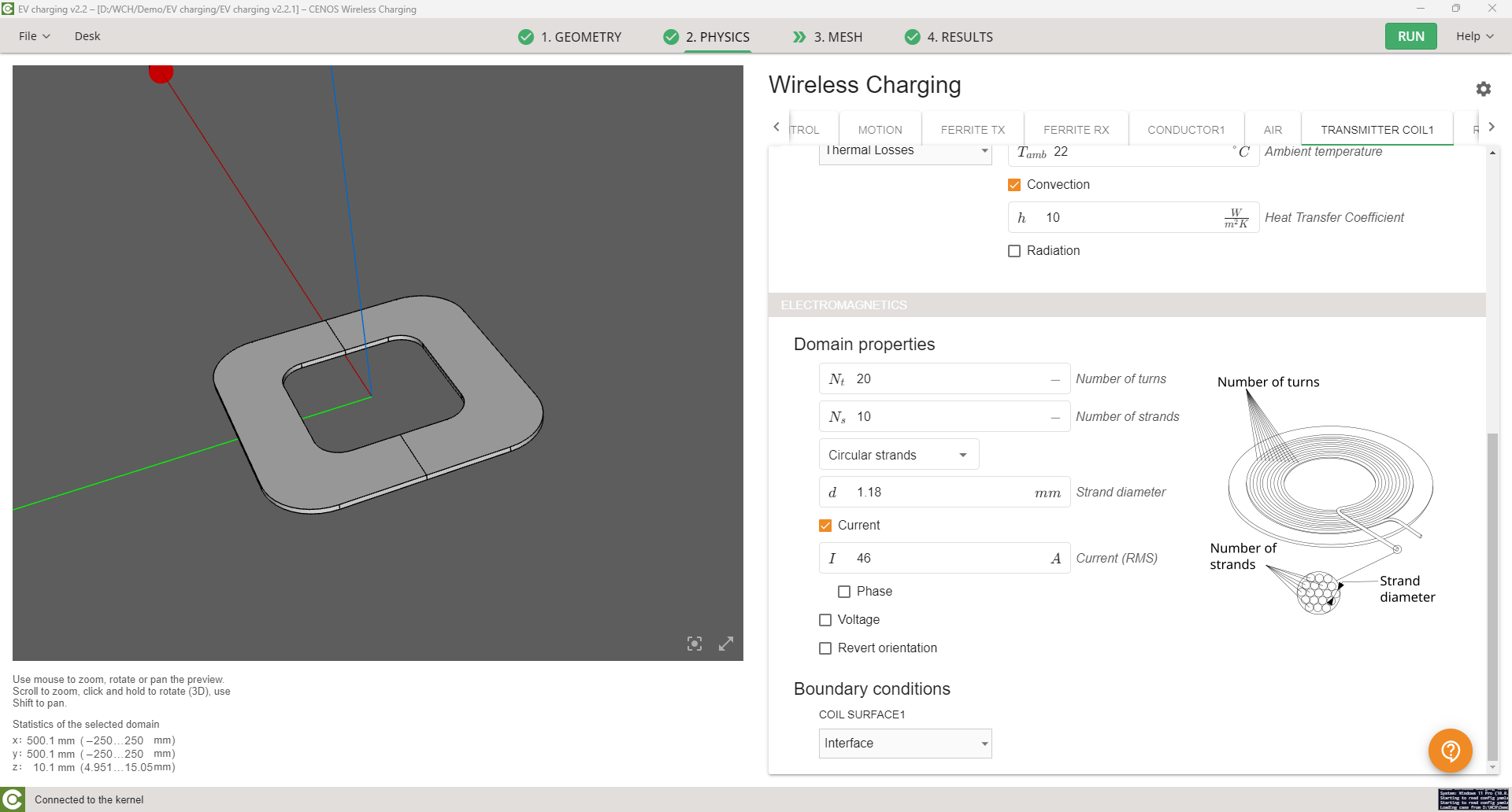
Transmitter coil properties:
- Coil configuration: The simulation displays the transmitter coil with domain properties that include the number of turns (Nt = 20) and the number of strands (Ns = 10), which affect the electromagnetic field generated by the coil.
- Current: The current passing through the coil is set to 46 A (RMS), one of the factors influencing the strength of the magnetic field and thus the efficiency of wireless energy transfer. In general, efficiency is the ratio between total power supplied and transmitted power, and it mainly depends on geometry and coil placement.
- Thermal management: Heat transfer properties are defined, including convection with an ambient temperature of 22°C, and natural convection losses are taken into account, which allows the simulation to account for thermal effects and how they may impact coil performance.
What Is the Solution?
Simulation software provides a way to model, test, and optimize wireless charging systems for electric vehicles without building too much of expensive and time-consuming physical prototypes. Through detailed simulations, engineers can evaluate how different design parameters, such as coil alignment, inductance, magnetic field distribution, and heat management, influence the overall performance of the charging system.
Here are three key images from simulation results that illustrate the effectiveness of this approach:
Image 1: Temperature distribution of the charging coil
This simulation illustrates the temperature distribution within the wireless charging system, focusing on the transmitter coil embedded in the ground. The color scale shows how heat builds up around the coils during the charging process.
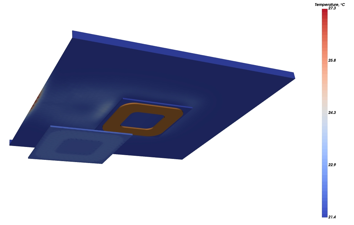
- Analysis: As energy is transferred from the transmitter coil to the receiver coil, a small amount of heat is generated, especially when the coils are misaligned. The simulation shows that areas of higher temperature occur near the transmitter coil, indicating where thermal management will need to be optimized to prevent overheating.
Image 2: Magnetic flux density
This simulation provides a cross-sectional view of the magnetic flux density between the transmitter and receiver coils. The magnetic field strength is visualized from low (blue) to high (red), showing the energy transfer efficiency between the coils.
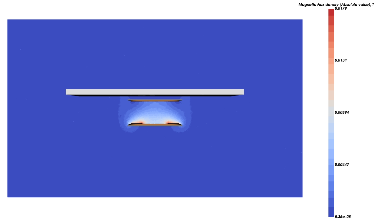
- Analysis: When the coils are properly aligned, the magnetic flux density is strongest directly between the coils, maximizing energy transfer efficiency. If the coils are misaligned, the flux density decreases, leading to less efficient energy transfer. This simulation helps engineers understand the importance of maintaining proper coil alignment.
Image 3: Magnetic field distribution with misalignment
This image shows the effect of coil misalignment on the magnetic field distribution. As the receiver coil shifts slightly from its optimal position and the magnetic field does not weaken. What we see is that the receiver coil is almost completely outside of the magnetic field generated by the transmitter coil, and the transmitter coil couples with the conductive plate instead. That causes bad coupling between the coils and increased losses in the conductive plate.
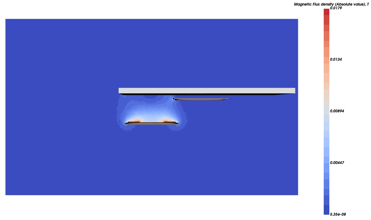
Analysis: When the coils are misaligned, the magnetic field becomes distorted, reducing energy transfer efficiency and leading to potential energy losses. The simulation highlights the need to design systems that account for real-world positioning variations.
These simulation results allow engineers to optimize both stationary and dynamic wireless charging systems by helping them visualize the impacts of alignment, heat generation, and magnetic field behavior.
What are the results?
The results from these simulations provide invaluable insights into how to design more efficient wireless charging systems for electric vehicles. The following diagrams present detailed analyses of key performance indicators that engineers can use to further refine their designs.
Diagram 1: Stray loss
The Stray loss diagram shows how energy losses vary across different components of the system, such as conductors and ferrite materials. The stray losses increase over time, with the largest losses occurring in the transmitter coil.
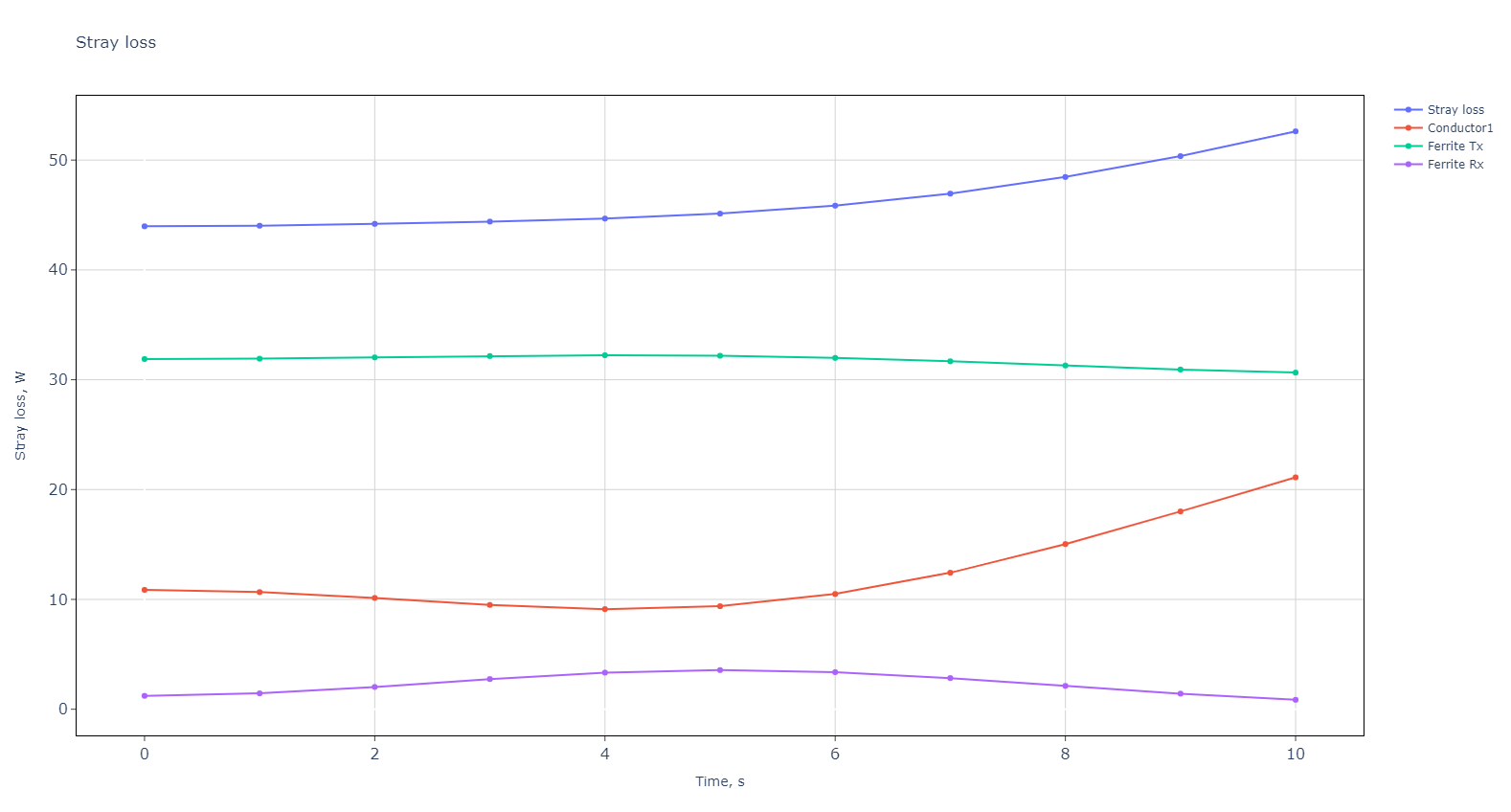
- Analysis: This chart shows that engineers must focus on reducing stray losses in the transmitter coil, as these contribute significantly to overall inefficiency. Managing conductive losses in particular is crucial for maintaining system performance.
Diagram 2: Mutual inductance
The Mutual inductance diagram illustrates how mutual inductance between the transmitter and receiver coils becomes worse over time, starting at -70 µH and rising to nearly 10 µH.
Initially the coils are perfectly aligned, and then, when they get further apart, the coupling becomes worse. Here we look at the absolute values, mutual inductance is better at the beginning, and worse at the end.
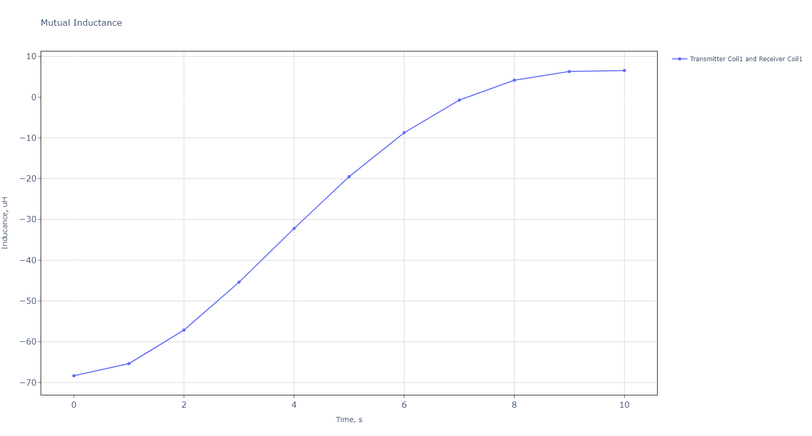
- Analysis: As the coils move into better alignment, the mutual inductance increases, improving energy transfer efficiency. This highlights the importance of designing systems that dynamically adjust coil positioning to maintain high mutual inductance.
Diagram 3: Coupling coefficients
The Coupling coefficients diagram shows how the coupling between the transmitter and receiver coils increases from -0.17 to near 0 over time.
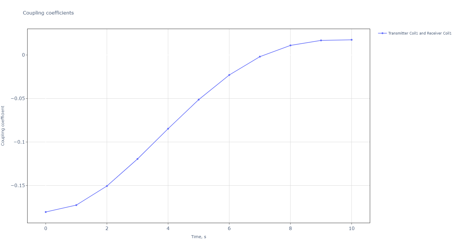
- Analysis: This demonstrates that the system’s ability to transfer energy gets worse significantly as the coils are not aligned. Coupling is better at the beginning, and in the end, when the absolute value comes close to 0, it is worse. Engineers can use this information to optimize coil design and system configuration for better performance.
Diagram 4: Q factor
The Q factor diagram compares the Q factor of both the transmitter and receiver coils. The Q factor of the transmitter coil is higher, peaking above 110, while the receiver coil maintains a lower Q factor around 106.
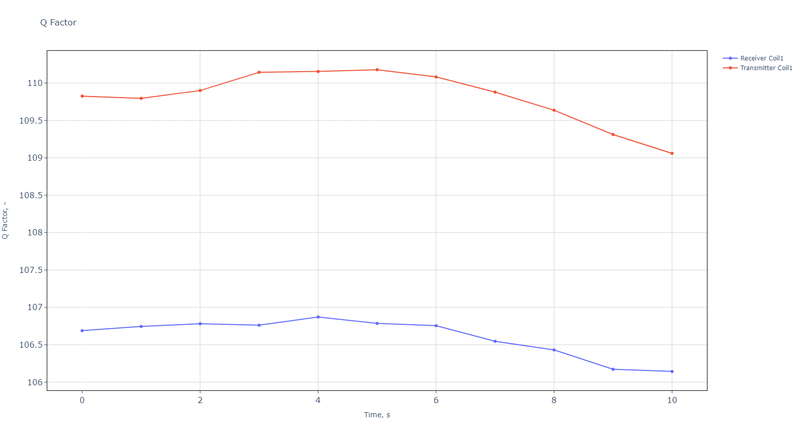
Analysis: A higher Q factor indicates fewer energy losses. This chart suggests that the transmitter coil is more efficient than the receiver coil, and optimizing the receiver coil’s design could lead to a more balanced system with fewer losses.
Diagram 5: Self Inductance
The Self inductance diagram highlights changes in self-inductance for both the transmitter and receiver coils over time. The transmitter coil’s self-inductance peaks at 386 µH, while the receiver coil’s inductance decreases steadily.
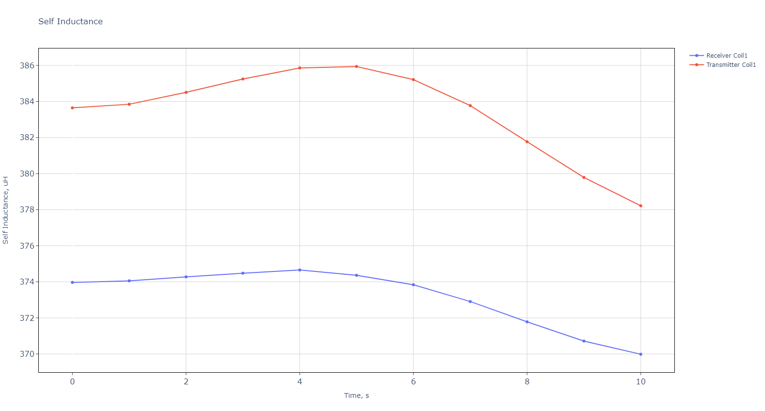
- Analysis: This decreasing self-inductance in the receiver coil could indicate increasing inefficiencies, making it important for engineers to address alignment issues or electromagnetic field interactions that could be reducing performance over time.
Wireless charging systems for electric vehicles hold potential for the future of mobility, offering a convenient and scalable solution to today’s charging infrastructure challenges. However, as seen in the simulation results and diagrams, there are significant challenges related to coil alignment, energy transfer efficiency, and thermal management.
Simulation software provides a powerful tool for engineers to model, test, and optimize these systems before implementing them in real-world applications. By understanding and addressing these challenges, engineers can design wireless charging systems that are more efficient, reliable, and ready to power the electric vehicles of the future.
At CENOS, we are proud to support customers who are developing these cutting-edge technologies. Our simulation software helps engineers design and optimize the complex coil systems required for both stationary and dynamic wireless charging solutions.
