Induction welding steady state: case study
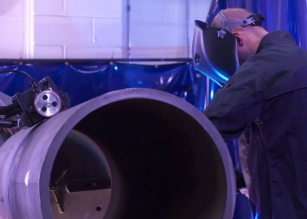
Induction welding is an efficient method used for welding sheets into tubes or pipes. This method is using high-frequency (HF) current. HF inductor induces alternating current in the tube, where the current concentrates at the joining place and generates a high amount of heat so that metal is melted.
The two edges of the sheet are brought together, and the heat from the high-frequency current causes the material to melt locally, creating a continuous welded seam as it forms into a pipe. This process is popular because it allows for high-speed, efficient welding with minimal waste and excellent control over the quality of the weld. However, it requires careful calibration and monitoring to make sure the material is heated correctly and evenly.
What is the challenge?
For manufacturers and engineers designing cutting-edge technologies, the challenge is not necessarily about welding itself but to guarantee consistent quality in every pipe that rolls off the line.
What makes this process stand out is its continuous nature. As the sheet moves forward, it’s progressively heated and welded into a solid tube. However, the balance between precision and power is important here.
The key to a perfect weld is achieving the right temperature: too little heat and the edges won’t fuse properly; too much, and the material melts excessively, compromising the pipe’s quality. Getting it wrong can result in significant energy waste and downtime.
The following images illustrate the process: the first image breaks down the different seam welding methods, while the second details the mechanics of the pressure rollers, impeder, and the “Vee” angle that controls the heating and welding.
This entire process is energy-intensive, and saving energy without sacrificing performance is the ultimate challenge. It’s here where precision, expertise, and continuous improvement play a critical role in optimizing both quality and energy use.
1. Tube butt seam and tube mash seam:
The image shows various methods of welding seams in pipes using induction heating.
- Tube butt seam (A and B): The edges of the tube material are aligned and heated via induction, as HF currents concentrate at the edges to create the weld. The induction coil wraps around the tube to evenly apply the current.
- Tube mash seam (C): A roller applies pressure to the heated edges, ensuring a solid weld forms as the tube travels through the process. The diagram highlights how HF currents are applied just before the roller compresses the seam.


2. Detailed tube welding process:
This image shows the mechanics of the welding process in more detail:
- Tube travel: The sheet material is continuously rolled into a tube as it moves forward.
- Pressure rolls: Two rollers compress the heated material at the point of welding, ensuring a tight, clean seam.
- Induction heating (sliding contacts): The high-frequency currents are applied to the seam’s “Vee” section, which is the narrow opening between the two sheet edges. The impeder inside the tube helps focus the current on the edges to maximize the heating efficiency.
- “Vee” angle and vee length: These parameters are crucial to control the welding process, ensuring that the material melts correctly and the resulting pipe is structurally sound.
What is the solution?
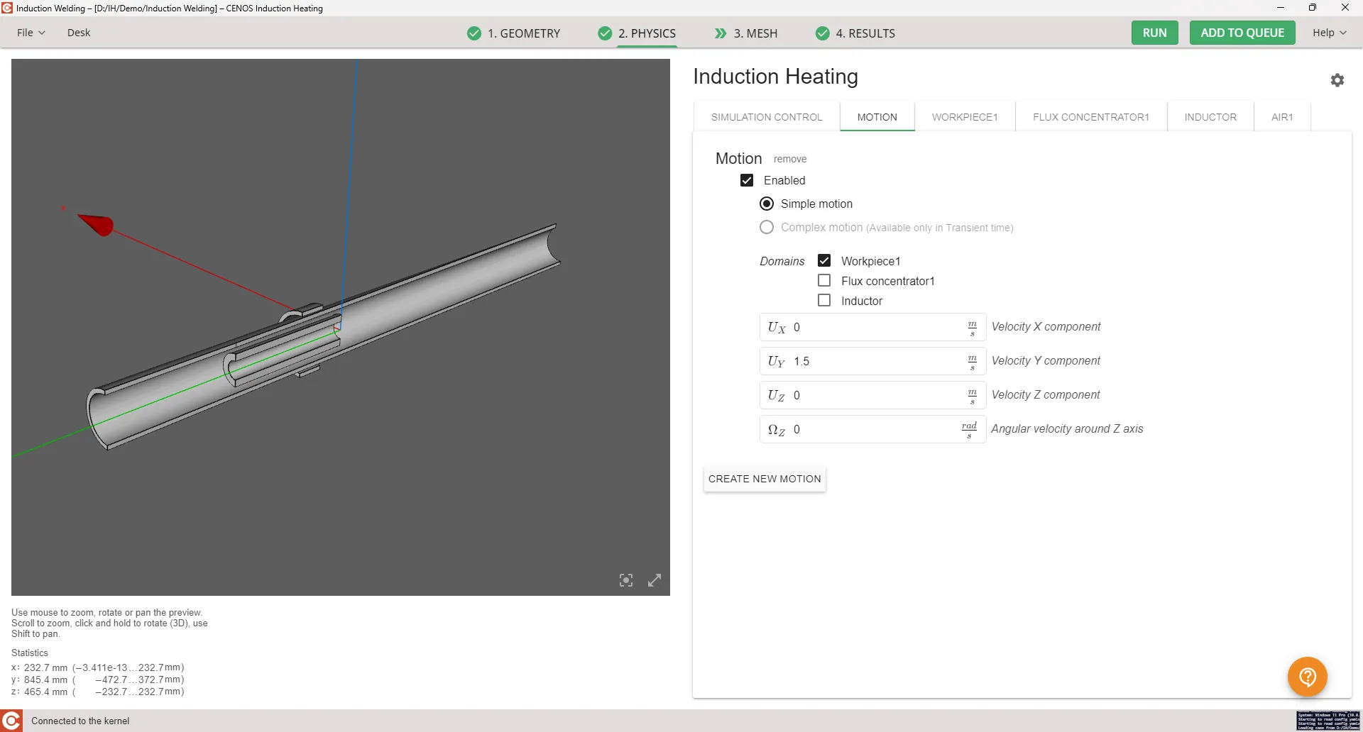
The simulation setup shown in the image is a detailed configuration for an induction heating process. The simulation interface is from CENOS, a software designed to simulate induction heating processes.
Here’s an analysis of what is happening in this simulation:
Overview of the setup:
- Workpiece (tube or pipe): The 3D model displayed on the left shows a cylindrical workpiece, a metal tube, which is being subjected to the induction heating process.Continuous motion is applied to model continuous process.
- Induction coil: Though the coil is not visually highlighted in the geometry, the induction heating is set to occur along a section of the tube where a welding seam would be created.
Key parameters:
Motion:
- Enabled: The motion of the workpiece is active, meaning the simulation considers the movement of the material during heating.
- Simple motion: This setting ensures a straightforward simulation of linear motion without complex dynamic changes. The tube is moving in a linear direction through the heating zone.
- Velocity components (Uₓ, Uᵧ, U_z):
- The Uᵧ velocity component is set at 1.5 m/s, which means that the workpiece is moving along the Y-axis at this speed. This simulates the continuous movement of the pipe through the induction coil.
Domains:
- Workpiece1: This represents the tube or pipe being heated and welded. It’s the main object being simulated.
- Flux concentrator: Not selected in this case, indicating that no flux concentrator is used to focus the magnetic field more intensively inside the tube. This choice impacts the distribution of the magnetic field in the workpiece.
- Inductor: In motion we apply only the movement of the workpiece, and we have flux concentrator and inductor present in the system.
Simulation process:
The workpiece (tube) moves at a velocity of 1.5 m/s along the Y-axis. The goal of the simulation is to observe how the heat is distributed across the moving workpiece, to support optimal conditions for welding the seam along the tube’s edge.
This type of simulation helps manufacturers predict:
- Heat distribution: Where the heat is concentrated and how evenly it is applied along the weld seam.
- Welding efficiency: Whether the tube’s movement speed matches the heating power to create a proper weld.
- Energy consumption: Since induction welding is energy-intensive, simulations can be used to optimize the process for better energy efficiency, ensuring the workpiece gets adequately heated without wasting energy.
In the first image, we see a cross-sectional view of the pipe where the temperature distribution along the weld seam is shown. In this simulation low carbon steel AISI 1020 is used, which melts at around 1515 degC. We see the maximum temperature of 1534, so we are just above melting temperature.
The blue areas represent the cooler regions of the pipe that remain unaffected by the heating process. This allows for energy-efficient heating, as only the necessary areas are heated to the required temperature.


Thermal analysis
Steady-state solution: The first image provides a thermal distribution view of the pipe during the induction welding process. This half-cut view focuses on the temperature profile as the induction coil heats the pipe. The color gradient, from blue (cooler) to red (hotter), visualizes how the temperature varies along the pipe.
- Temperature hotspot: The red section along the seam indicates the melting and welding point where the temperature reaches around 1534 degC. This is the point where the edges of the pipe fuse together to form a welded seam. The blue areas show the lower temperatures surrounding the weld, which gradually cool down as the pipe moves away from the heating zone.
- Continuous process: The simulation captures the continuous motion of the pipe through the induction coil. As the workpiece progresses, the area at the weld seam gets heated precisely at the joint for optimal temperature for solid-state welding. This steady-state result is important for manufacturers to monitor the thermal efficiency during production.
- Magnetic flux concentrator: The green section represents the flux concentrator, which plays a important role in focusing the magnetic field around the seam area, making sure that the energy is directed efficiently to the joint, reducing energy losses and improving the heating focus. The simulation shows how the concentrator is positioned to concentrate the power directly where it is needed for melting and welding.
The second image shows the full pipe thermal distribution, where the weld seam (highlighted by a thin red line) indicates the concentration of heat at the necessary point of contact. This visualization allows engineers to apply the heat efficiently, avoiding overheating or underheating.
CENOS simulation advantages:
The ease of setting up this simulation using CENOS simulation software is very well shown here. Engineers can quickly upload the CAD file, set up parameters like motion and heating power, and run the simulation to get steady-state results in a short time. The detailed thermal analysis ensures that the welding process can be optimized, saving both time and energy.
Magnetic field distribution:
This final image illustrates the magnetic field distribution surrounding the pipe during induction welding. The blue rings around the tube represent the magnetic field intensity generated by the induction coil, while the orange region represents the inductor. The green area within the pipe is the flux concentrator, which helps focus the magnetic field to the seam to support maximum heating efficiency at the weld point.

The flux concentrator is important in focusing the magnetic field only on the seam, so that the pipe is welded properly while minimizing energy waste. The white-hot area in the center shows the highest concentration of heat, which is the point of welding.
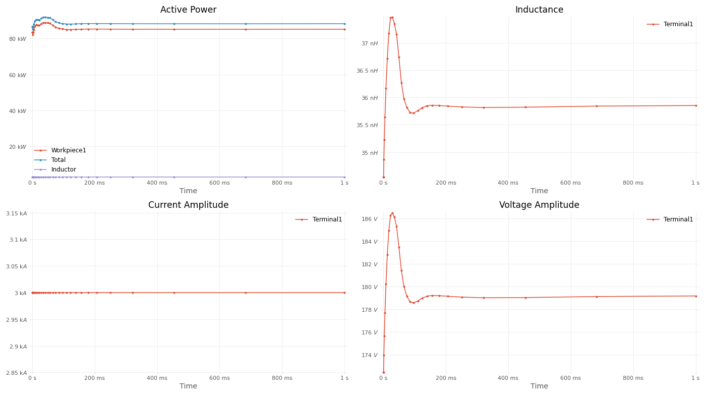
These graphs show how the electrical parameters—power, inductance, current, and voltage—behave as the induction welding process transitions from the initial transient phase to a steady-state condition:
- Initial fluctuations: During the first 200 milliseconds, all parameters (particularly power, inductance, and voltage) show noticeable fluctuations. This is due to the system stabilizing as it heats the workpiece and adjusts the magnetic fields to the correct levels.
- Steady-state behavior: After this transient phase, all parameters stabilize, with:
- Power remaining consistent at around 80 kW.
- Inductance leveling off at 36 nH.
- Current remaining steady at 3 kA.
- Voltage stabilizing at 178 V.
This behavior is important for engineers to make sure the system runs efficiently. Once the system reaches the steady-state, it can continue to operate with consistent power transfer and stable electrical parameters, resulting in efficient heating and optimal welding quality.
What is the result?
By using CENOS Induction Heating simulation software, engineers can optimize the induction welding process for efficiency and quality. This simulation helps engineers visualize key parameters such as:
- Temperature distribution along the seam.
- Magnetic field behavior and how it affects heat generation.
- The effectiveness of the flux concentrator in focusing energy precisely where it is needed.
Benefits of simulation:
- Precision control: Engineers can visualize exactly how the heat is distributed along the pipe seam, making sure the welding process is efficient and produces high-quality results.
- Energy efficiency: The simulation helps minimize energy use by showing where power is being consumed. By adjusting the inductor placement and flux concentrator, engineers can significantly reduce energy waste.
- Quick setup and results: Using CENOS, engineers can easily upload a CAD file, configure the simulation parameters, and run simulations that generate steady-state results in a short amount of time. This allows for fast iterations and optimizations, reducing downtime and improving production speed.
Why it’s important for engineers:
Induction welding is an energy-intensive process. However, with the use of simulation software, engineers can optimize the process to save energy, increase productivity, and guarantee weld quality. The detailed insights by these simulations allow engineers to anticipate potential problems before they occur in real-world production, reducing errors, waste, and costly rework.
