Induction heating of turbine blade: case study
Turbine blades in aircraft engines endure extreme operational conditions, where high speeds and temperatures expose them to potential damage from small particles, dust, and debris. Over time, these impacts can deform the blade tips, compromising their aerodynamic efficiency and rendering them unfit for use.
However, rather than discarding damaged blades, modern renewal techniques allow engineers to repair them by reshaping the tips. The critical first step in this process is heating the damaged tip to a uniform temperature, enabling precise reshaping to restore its original form and functionality.
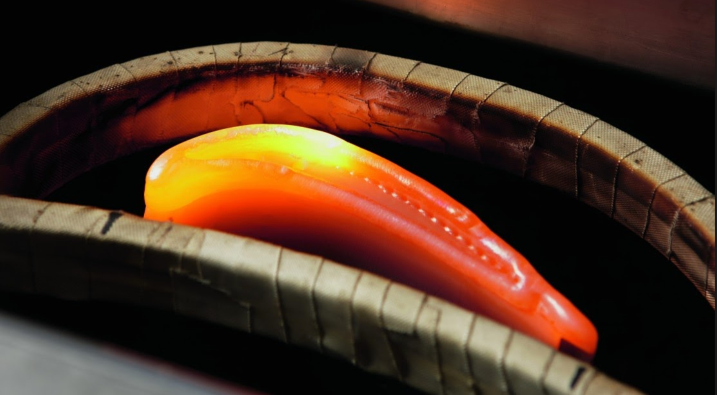
The simulation featured in this case study highlights the application of induction heating to achieve this goal. Unlike preheating for welding, the primary objective here is to ensure even temperature distribution across the blade tip for optimal reshaping.
By using simulation technology, engineers can overcome the inherent challenges of heating complex geometries and develop efficient, scalable solutions to renew turbine blades for continued use in aircraft engines.
This case study explores the challenges, solutions, and results of this innovative application.
What is the challenge?
Turbine blades are engineered for reliability, operating under high pressure and temperatures. However, during operation, small debris and particles can strike the blades, particularly their tips, causing deformation or damage. This damage disrupts airflow, reduces engine efficiency, and risks further operational issues. To renew the blade, its tip must be reshaped to its original form. This reshaping process begins with heating the damaged area to a uniform temperature.
The challenges in this process include:
- Achieving uniform temperature distribution: The blade’s intricate geometry and material properties make it difficult to ensure consistent heating, especially at the tip.
- Preventing material defects: Overheating or uneven heating can weaken the blade’s microstructure, leading to cracks or reduced durability during operation.
- Efficiency and speed: Traditional trial-and-error methods for heating optimization are slow and inefficient, delaying repair timelines.
- Scalability: Aircraft engines have hundreds of blades, requiring repeatable and reliable heating processes.
Without precise control, these challenges can result in poorly repaired blades, making them unsuitable for reuse.
What is the solution?
The solution lies in leveraging simulation-driven induction heating processes. Simulation software enables engineers to model and optimize the heating process virtually, accounting for the blade’s geometry, material properties, and thermal requirements.
Using simulation tools:
- Engineers can design optimized inductors: By virtually testing coil designs, engineers can ensure uniform temperature distribution across the blade tip, reducing hotspots or cold spots.
- Simulations provide precise thermal control: Advanced algorithms predict how electromagnetic fields interact with the blade, achieving consistent heating patterns.
- Time and cost are minimized: By simulating the entire process, engineers can eliminate costly physical prototypes and accelerate repair workflows.
Let’s take a look into the simulation, using CENOS Induction Heating simulation software.
In this quick animation, we actually demonstrate 10 design iterations. You can see the coil shape design changes and how it affects the heating process. With CENOS this is a quick and simple automated process. You can use virtually any CAD modeling software of your choice.
The colors indicate the areas of uniform heating across the blade tip, ensuring the material is evenly prepared for reshaping. The virtual design allowed for optimal inductor placement, reducing energy waste and avoiding overheating sensitive areas.
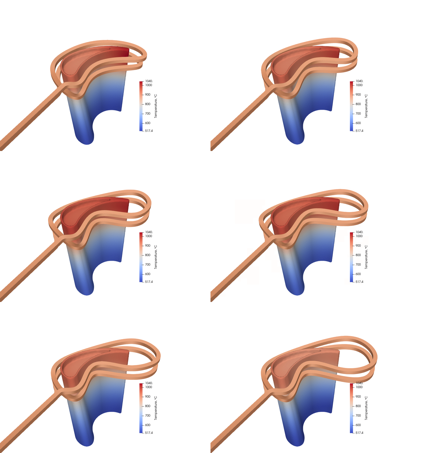
In the first iterations, you can see that the first coil design heated the trailing edge of the blade way too much. It may not be intuitive how much larger the coil should be, but simulation helps you to determine the exact size.
As you can see, the inductor around the trailing edge had to be made significantly larger to achieve uniform temperature. Due to more uniform heating, the heating time was also reduced from 125s to 50s thus saving the welder’s time.
This also saves the machinist’s time. While this inductor is relatively simple, testing different geometries in the lab would be much, much more time consuming and expensive. Simulation also allows to quickly test other turbine blade geometries with the same inductor.
By simulation software, engineers can:
- Optimize inductor design: Quickly iterate and refine coil designs to achieve uniform heating.
- Predict temperature distribution: Accurately model heat flow within the blade, eliminating trial-and-error guesswork.
- Save time and resources: Complete optimization in hours instead of weeks, reducing costs and speeding up production cycles.
The simulation software ensures that every detail, from the blade’s geometry to its material properties, is factored into the design. This process not only improves efficiency but also minimizes the risk of defects during welding or other downstream processes.
Analysis of the simulation
Let’s look into some more details of this simulation.
Magnetic flux density in the induction heating process
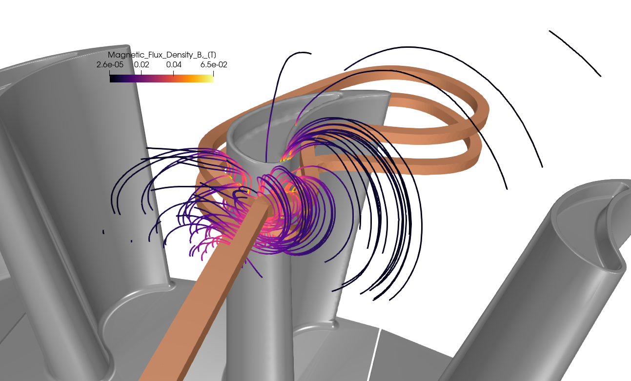
Key insights:
- This image illustrates the magnetic flux lines generated during the induction heating process around the turbine blade.
- The intensity of the magnetic flux density is color-coded, showing areas of higher flux concentration near the inductor coils.
- Engineers can identify how the electromagnetic fields interact with the blade, pinpointing regions of effective heat transfer.
Value for engineers:
- Visualizing the magnetic flux density helps engineers optimize the placement and geometry of inductor coils for uniform heating.
- It provides insights into reducing energy losses by minimizing areas of excessive flux leakage or hotspots.
Heat distribution and current density visualization
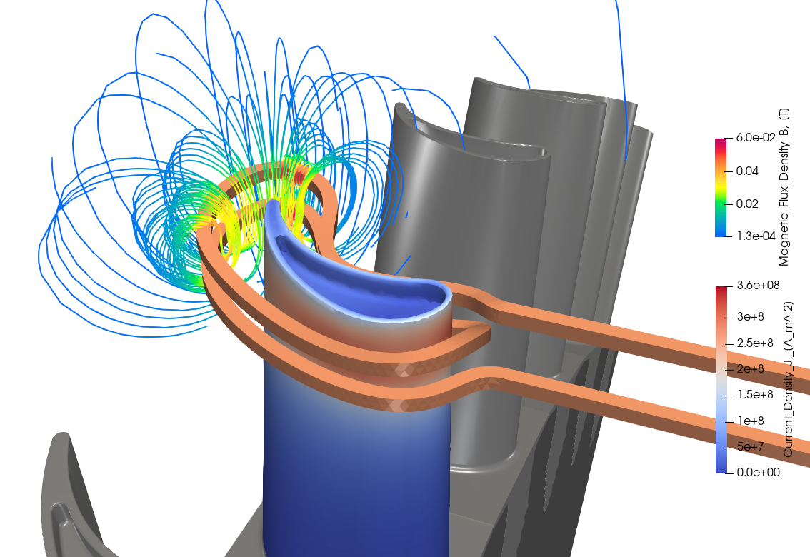
Key insights:
- The image displays the thermal distribution on the turbine blade’s surface, with a gradient indicating temperature changes from the base to the edges.
- Current density is overlaid, showing how electric currents flow through the material to generate heat.
- Areas of high temperature correspond to regions of higher current density, emphasizing the role of induction currents.
Value for engineers:
- Engineers can evaluate whether the heating is uniform across the blade’s complex geometry.
- It assists in determining the effectiveness of inductor design and material conductivity in achieving desired temperature profiles.
Visualization of current density and flow
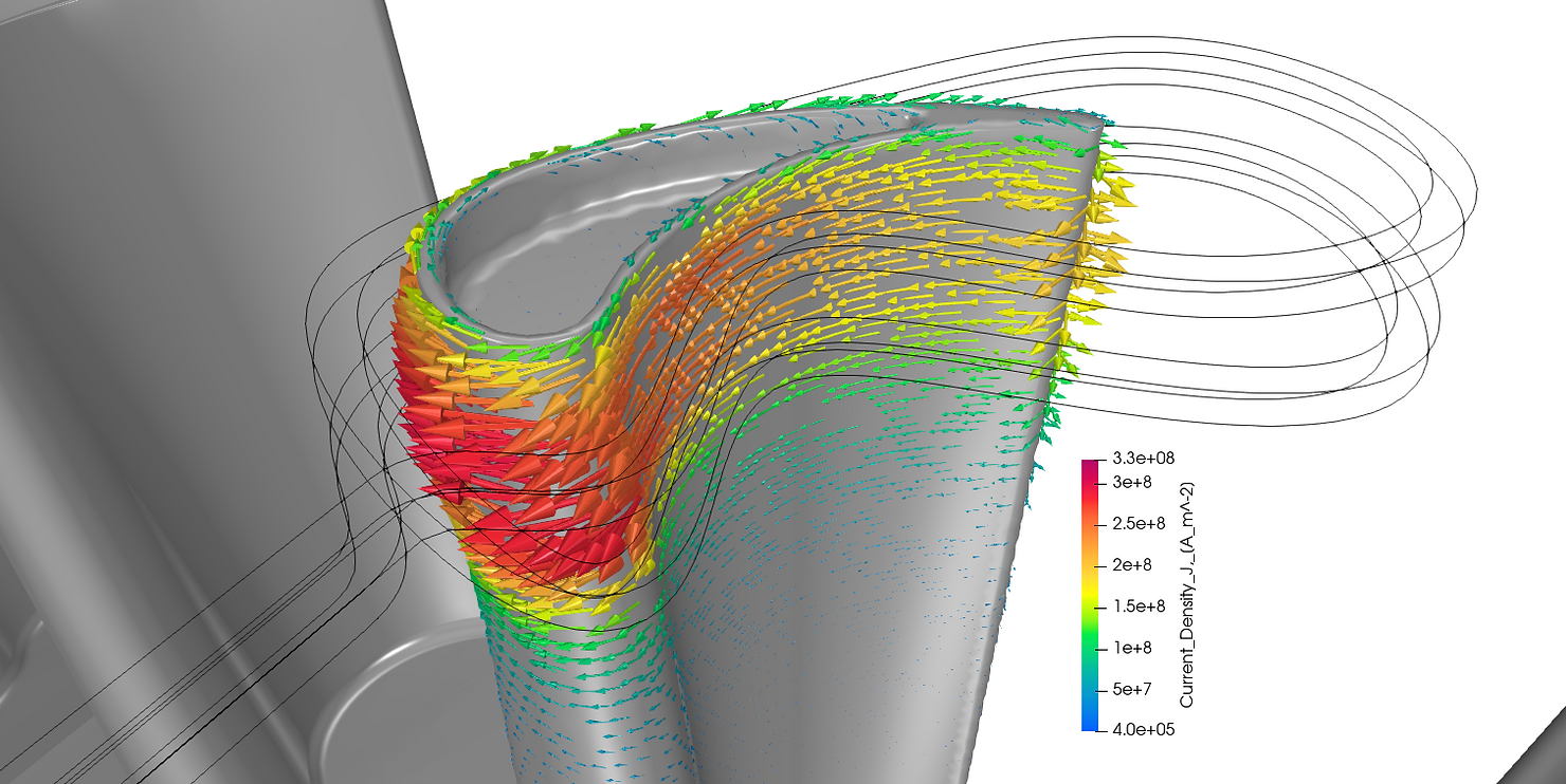
Key insights:
- This image provides a more detailed view of the current density distribution within the turbine blade, overlaid with directional flow lines.
- The gradient highlights regions where eddy currents are most intense, which are crucial for localized heating.
- The direction of current flow helps engineers understand the interaction between the inductor’s magnetic field and the workpiece.
Value for engineers:
- This visualization allows engineers to refine inductor coil configurations to avoid areas of insufficient or excessive heating.
- It aids in troubleshooting issues such as uneven temperature distribution or energy inefficiency by identifying problematic areas in the design.
What is the result?
By using simulation-driven induction heating processes, manufacturers can renew turbine blades with exceptional precision and efficiency. The results speak for themselves:
- Uniform heating: Damaged blade tips are heated to consistent temperatures, ensuring the reshaping process restores the blade to its original condition.
- Extended blade lifespan: The risk of microstructural damage is minimized, maintaining the blade’s integrity and extending its operational life.
- Faster turnaround times: Simulation reduces repair time by enabling engineers to perfect the heating process virtually, saving weeks of trial-and-error adjustments.
- Cost savings: Reusing turbine blades instead of manufacturing replacements significantly reduces costs for aircraft operators.
This approach is a good option for industries where turbine blade reliability is non-negotiable, such as aerospace and power generation. By combining induction heating with simulation technology, engineers can confidently repair damaged components, keeping aircraft engines efficient and operational.


