Induction hardening for electric vehicles: case study
The world of electric vehicles (EVs) is evolving fast. The cars you are driving on petrol now have all-electric versions or hybrid. Most probably, the traffic we see today will turn into fully electric in upcoming years. With all that, there are multiple challenges that arise in manufacturing parts that require specific durability and efficiency standards.
Induction hardening is important in creating wear-resistant surfaces in EV components like drive joints. Over the past decades, significant investments have been made to establish production lines and supply chains for automotive parts. Now, suppliers aim to repurpose these lines to produce parts for electric vehicles (EVs). However, EVs come with different hardening requirements due to their higher torque demands, which necessitate deeper hardening.
This raises critical questions: How can suppliers redesign hardening recipes and coils to meet the needs of EVs? Can they achieve this using the same power supplies, originally designed to operate within specific frequency and power ranges?
In other words, how can the hardening process be optimized within the constraints of legacy power supplies, thereby avoiding costly capital investments?
In this particular simulation case study, we will take a closer look into how simulation can help with impedance mismatching in EV part induction hardening.
What is the challenge?
The core challenges include meeting new mechanical standards, developing specialized “heating recipes” to achieve precise hardening zones, and ensuring that impedance matches between the source (generator) and load (inductor + workpiece). Matched impedance ensures the efficiency of the setup. If the impedance is not matched, the coil gets excessive heating, and a lot of energy is wasted. So, it is about energy efficiency.
Designing coils with appropriate inductance and adjusting the system’s electrical circuit to align with the specified parameters are the first steps to maximize power transfer.
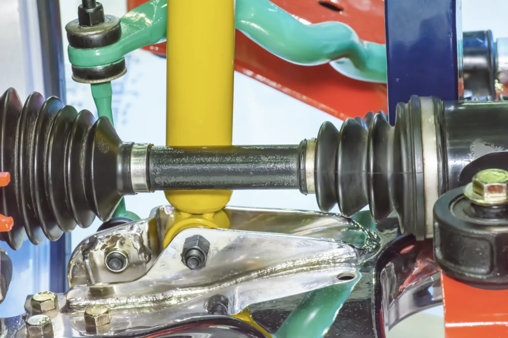
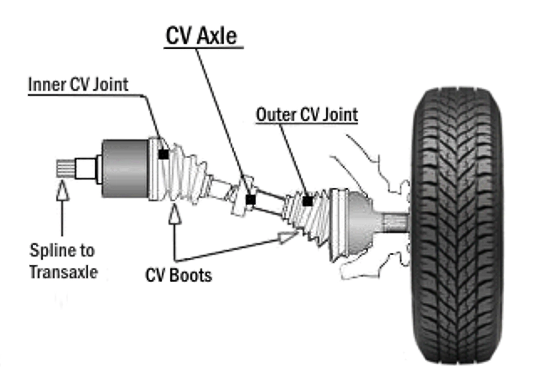
There was a production line dedicated to hardening CV joints. Now, the supplier, GKN Drivetrain Celaya in this case, aimed to supply these same CV joints for electric vehicles (EVs). However, EV manufacturers require a deeper hardening zone to accommodate the higher torque demands of EVs.
GKN Drivetrain Celaya manufacturing engineer Kevin Tovar Estrada wanted to meet these requirements without investing in costly line upgrades, instead focusing on adjusting the parameters of the hardening process.
This article explores how simulation technology aids in this process. One critical aspect is impedance matching, and simulation provides a way to measure and optimize impedance effectively, making sure that adjustments meet the new requirements without extensive physical modifications.
Unlike parts in internal combustion vehicles, EV components demand a hardening zone depth of 5 mm (0.20 in), an upgrade from the previous 3 mm (0.12 in). This increased depth requires recalibrated heating frequencies and timing, alongside precise equipment adjustments, to deliver the desired outcome.
What is the solution?
Engineers and manufacturers can address challenges by using simulation software made for induction hardening. Simulation software, like CENOS, provides a practical and efficient solution for testing and optimizing parameters before committing to actual production setups.
In this case study, the simulation software plays a vital role in testing different frequencies and heating times to achieve the 5 mm hardening zone required for EV joints. Engineers can simulate adjustments such as altering the flux concentrator placement, modifying capacitor values, and fine-tuning heating frequencies.
For instance, in the EV joint hardening process, parameters shift to a lower frequency (5 kHz), maintaining 60 kW power with a slightly extended heating time (6 seconds) to achieve the correct hardening profile and depth. Simulation provides engineers with visual feedback, showing how current density shifts during the heating process, and enables fine adjustments to coil designs to match impedance accurately.
Parameters for ICV and EV joint hardening
ICV parameters:
- 12 kHz
- 60 kW
- 5 sec heating time
- Hardening zone: 3 mm (0.12 in)
- Hardening profile: 750 °C (1382 °F)
- Inductance range: 60-100 nH
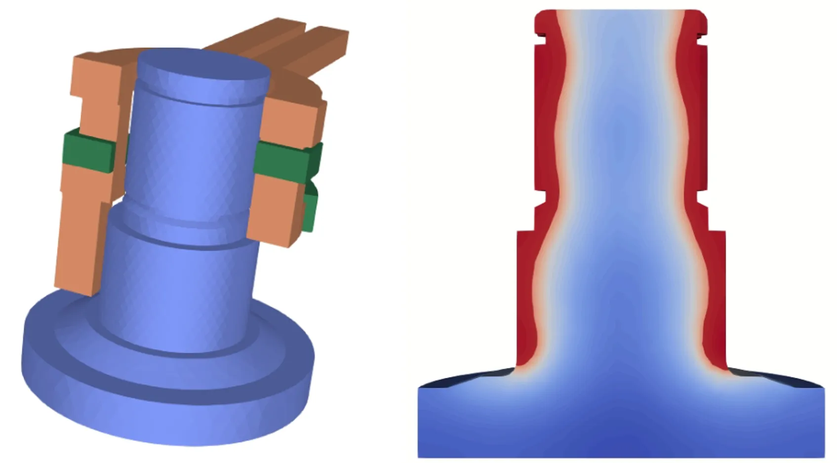
The red areas indicate regions reaching high temperatures, nearing the target hardening temperature of 750 °C (1382 °F), while the blue areas show cooler zones unaffected by the heating process. With ICV parameters of 12 kHz frequency, 60 kW power, and a 5-second heating time, this profile achieves a hardening depth of 3 mm (0.12 in), ensuring the component’s surface gains durability and wear resistance.
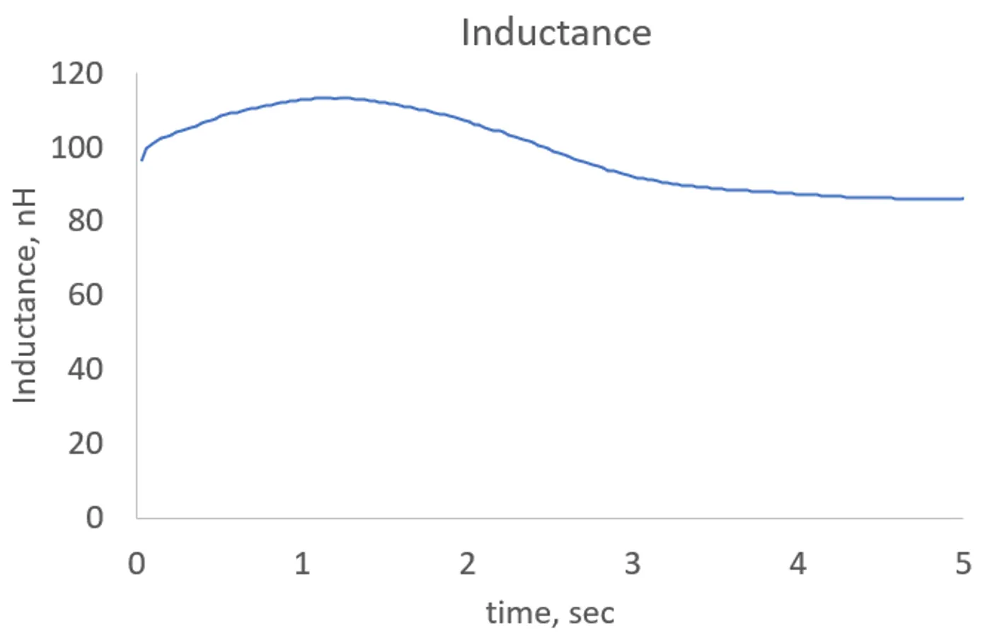
The graph shows the inductance over time during the heating process, with the inductance starting around 100 nH, then slightly decreasing and stabilizing within the target range of 60-100 nH. This variation indicates a successful impedance match between the power source and the load (inductor + workpiece) throughout the process.
Maintaining inductance in this range is crucial for optimal power transfer, ensuring that the heating is efficient and the desired hardening depth is achieved consistently.
EV parameters:
- 5 kHz
- 60 kW
- 6 sec heating time
Here’s how to achieve a deeper hardening profile with 5 kHz, 6 second heating time.
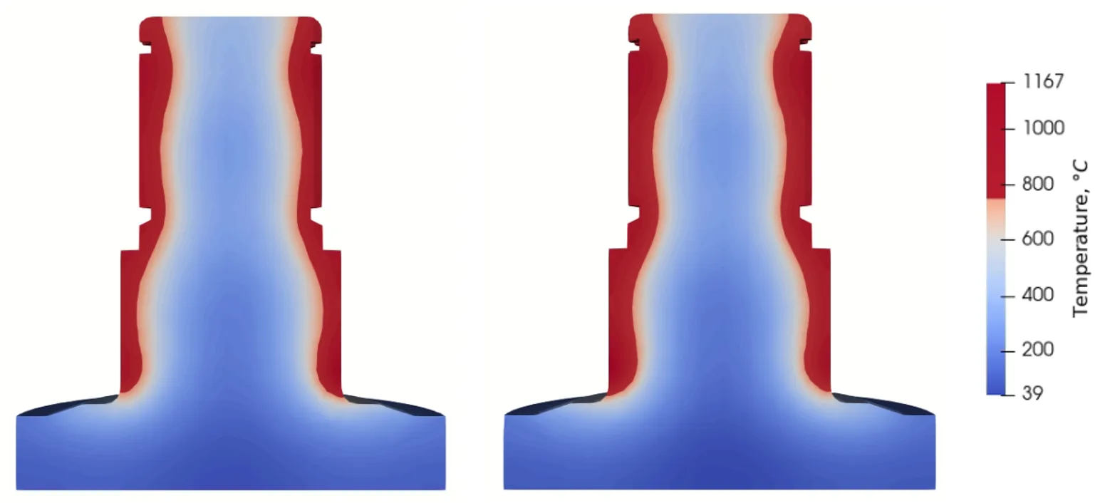
Compared to the internal combustion vehicle (ICV) parameters, the 5 kHz frequency and extended heating time of 6 seconds result in a deeper hardening profile, visible in the more extensive red regions near the surface. This higher temperature area, exceeding 750 °C (1382 °F), indicates that the heat penetrates further, ensuring a broader and deeper hardening zone that aligns with the specifications for EV components requiring increased durability.
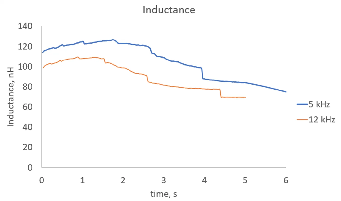
The inductance graph compares the EV (5 kHz) and ICV (12 kHz) settings over time. For the 5 kHz configuration, the inductance starts higher, around 120 nH, and gradually decreases to around 80 nH by the end of the 6-second heating time.
This pattern contrasts with the 12 kHz configuration, which maintains a slightly lower inductance level and stabilizes more quickly. The higher initial inductance for the 5 kHz setup allows for a more efficient power transfer, achieving the desired deeper hardening profile required for EV applications.
What is the result?
We can examine how current density changes throughout the process. The current density distribution images illustrate how the choice of frequency and heating time affects the induction heating process for EV parts. Here’s a comparison and analysis of the results across different settings.
12 kHz, 0.5 sec
- The current density is concentrated around the edges of the part, with relatively high values (up to 4.4e+08 A/m²) near the surface and a rapid drop-off toward the interior. This indicates a shallow heating profile that primarily affects the surface, with minimal penetration into the material’s core.
- The short heating time combined with the high frequency results in a surface-focused heating pattern, insufficient for achieving the deeper hardening profile needed for EV components.
5 kHz, 0.5 sec
- The current density distribution at 5 kHz and 0.5 seconds is similar in profile to the 12 kHz setting but slightly less concentrated at the edges. The lower frequency causes a marginally deeper penetration, although the effect remains primarily surface-level.
- This setup also does not meet the deeper hardening requirements for EV parts, as the short duration limits heat penetration into the material.
12 kHz, 5 sec
- Extending the heating time to 5 seconds at 12 kHz shows a more pronounced penetration of current density compared to the initial 0.5-second setting. The current density now reaches further into the part, with red zones extending deeper, indicating increased energy absorption.
- However, while there is an improvement in depth, the high frequency still limits the extent of penetration compared to lower-frequency settings. This setup offers better results than the shorter duration but may still fall short of EV hardening requirements.
5 kHz, 5 sec
- At 5 kHz and 5 seconds, the current density penetrates significantly deeper into the part. The distribution shows a well-balanced spread from the surface toward the core, with values reaching around 7.8e+07 A/m².
- This setup aligns well with the requirements for EV parts, as the combination of lower frequency and longer heating time allows for substantial depth in the hardening zone. The current density is more evenly distributed, achieving a more robust and deeper hardening profile ideal for EV component durability.
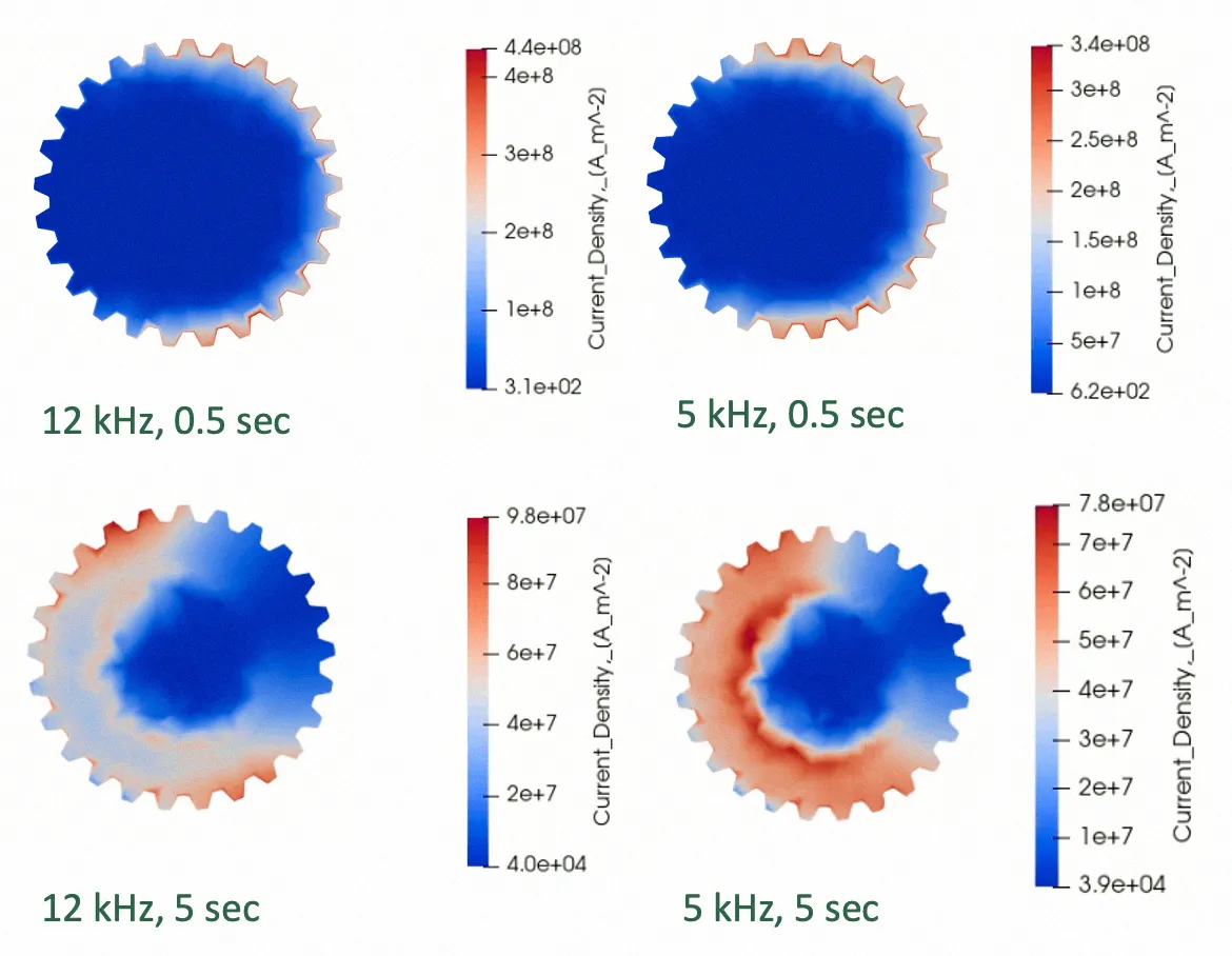
The simulation results indicate that for EV parts requiring a deeper hardening profile, the 5 kHz, 5-second configuration is optimal. This setup enables the current density to penetrate deeply and uniformly, creating a hardening layer that enhances part durability and meets EV-specific demands.
Using simulation technology, engineers gain critical insights into the precise dynamics of induction hardening for EV components. By simulating different setups, they can confidently adjust parameters like frequency and power, knowing these changes align with the stringent requirements of EV part specifications. This process ensures that the end product meets durability and performance standards with a deeper hardening profile essential for EV applications.
The visual analysis from simulation images further validates each stage, from initial setup to the final hardening result, showing the exact placement and behavior of components like the flux concentrator. This simulation-driven approach not only accelerates the design process but also reduces the need for costly and time-intensive physical prototypes, enabling engineers to bring efficient, reliable, and optimized EV parts to market faster.
