Induction channel furnace and induction crucible furnace: case study
In this case study, we will explore the challenges of electromagnetic melting and stirring of liquid metals in induction channel furnaces. We present a solution through advanced simulation and conclude with the critical results engineers can achieve using such simulation tools.
What is the challenge?
When dealing with industrial applications of induction channel furnaces for melting and stirring of metals, the most known challenges are the following:
- Uniform temperature distribution: Making sure that the liquid metal maintains a consistent temperature across the entire furnace is important for producing high-quality products and to keep the energy costs under control. Uneven temperature distribution can cause cold spots; cold spots can lead to local solidification; overheating in the majority of cases, results in higher energy consumption, as well as may lead to refractory erosion, leading to final product defects of excessive energy consumption.
- Efficient stirring and flow: Metals must be thoroughly mixed to avoid impurities or variations in composition. The electromagnetic fields used to stir the molten metal must generate the right flow patterns to ensure that the metal circulates efficiently.
- Heating and flow: For the induction channel furnace, heating and flow are generated in the channel. If there is not enough mixing, the bath above is still; there is no mixing there, and it stands to solidify from above. So, engineers look to produce enough stirring and heat in the channel to have sufficient movement and mixing in the bath as well.
- Energy optimization: High energy consumption is a concern for engineers when working with induction furnaces. Efficient heating and circulation help reduce energy usage while maintaining performance.
It is clear that it’s impossible to look inside the liquid metal container and understand how the liquid metal behaves. Without a clear understanding of how electromagnetic fields interact with the liquid metal, these challenges can lead to inefficient processes, higher costs, and inconsistent product quality.
What is the solution?
To deal with these challenges, engineers use simulations that model the behavior of molten metals in the induction channel furnaces under the influence of electromagnetic fields. These simulations provide a detailed look into how metals circulate, how heat is distributed, and where electromagnetic forces are most effective to drive the flow.
We created the following simulation to analyze the challenge.
Low-frequency induction channel furnace system simulation was done to evaluate system behavior with a specific furnace and coil geometry and applied frequency. Channel furnace with a 20 turn coil and ferromagnetic core was modeled.
Within the furnace, liquid aluminium was placed and electromagnetic stirring was initialized from molten aluminium state to analyze fluid dynamics, thermal distribution and mixing within the furnace. 50 Hz 20 kA current was used.
Numerical mesh was generated automatically, and then manually refined to capture in more detail aluminium behavior specifically in the channel part. In results a small temperature increase can be seen in the channel section of the furnace, which, coupled with the vortex-like aluminium flow created in the channel, distributes the heated aluminium in the rest of the furnace volume.
Insights of the simulation:
- Velocity and flow patterns: In the first image, a simulation of the induction channel furnace shows the velocity distribution of the molten metal. The color gradient (blue to red) reveals how fast the liquid is moving at different points in the furnace. The U-shaped channel at the bottom clearly shows that the liquid metal is being driven into a vortex by electromagnetic forces, ensuring constant movement and efficient mixing.


- Electromagnetic field interaction: In the second set of images, we see how the magnetic field interacts with the molten metal. The heat and flow velocity in the channel are illustrated in color, showing that electromagnetic forces are concentrated in the channel, driving a circular flow. This flow pattern prevents the liquid from settling and ensures that the metal is constantly moving, thereby reducing the risk of uneven heating or metal solidification.


- Heat distribution: The temperature distribution, highlights how the furnace maintains a consistent temperature. The black-and-yellow gradient demonstrates uniform heat throughout the liquid metal, a critical factor in keeping metal liquid in an energy-efficient way. Thus, the heat is generated just in the channel. There should be enough stirring to ensure the flow goes out to the bath and mix it properly. Nevertheless, too much stirring and high temperature can cause erosion of the refractory materials in the channel walls. The ability to control and predict temperature distribution enables engineers to design more energy-efficient furnaces that prevent overheating or underheating.
Velocity Field:

- The color scale on the image represents the velocity of the molten metal.
- The blue and green colors indicate slower flow regions, while the red/pink spots represent areas where the liquid metal is moving at higher velocities.
- The U-shaped path below the main body is the channel, where the molten metal circulates. This is typical in induction channel furnaces where the liquid metal is driven to move by electromagnetic forces.
- The distribution shows that the liquid metal flow is mostly steady but has some variations in velocity, which is critical for ensuring that the metal is continuously mixed and heated evenly.
Temperature Field:

- The image shows the temperature distribution in the liquid metal, with the temperature color scale.
- This image shows the uniform heating of the liquid metal. The very narrow temperature range indicates that the furnace is designed to maintain a very consistent temperature throughout the metal, preventing hot spots or cold zones.
- The black background with lighter areas indicates a steady heat distribution across the channel, suggesting that the furnace’s design is efficient at keeping the metal molten and stable.
These simulations help engineers visualize and improve furnace designs, optimizing the performance of electromagnetic stirring systems for different metals and applications.
What is the result and why is this simulation useful for engineers?
The result of this simulation is a detailed understanding of the electromagnetic melting and stirring processes in an induction channel furnace. Engineers can see how the liquid metal flows, where heat and electromagnetic forces are concentrated, and how different design choices impact energy efficiency and product quality.
Why is this simulation useful?
- Improved design for uniform heating: The simulations clearly show that uniform heat distribution is achievable by optimizing electromagnetic induction patterns. Engineers can fine-tune the inductor and channel designs to ensure no areas are left underheated or overexposed to the electromagnetic fields. This leads to better-quality castings, reduced waste, and improved overall product performance.
- Enhanced mixing and flow control: By visualizing the flow of liquid metal in real-time, engineers can determine how efficiently the metal is stirred within the furnace. This eliminates inconsistencies in the metal’s composition, ensuring homogeneity in the final product.
- Energy savings: The insights gained from these simulations allow engineers to optimize the furnace design for energy efficiency. Since the simulations provide a precise picture of where and how heat is distributed, the furnace can be adjusted to use only the energy required to achieve the desired temperatures, reducing operational costs.
- Predictive maintenance and troubleshooting: With a clear understanding of how the molten metal and electromagnetic fields interact, engineers can predict where potential failures might occur, such as areas prone to overheating or insufficient stirring. This predictive ability leads to better maintenance schedules and reduces the likelihood of costly downtime.
In the following case study we will simulate and analyze the induction crucible furnace using CENOS simulation software.
What is the challenge here?
In industrial metallurgy, one of the critical challenges is ensuring uniform heating and mixing of molten metals, particularly in induction furnaces used for processes like melting and alloying. Achieving consistent temperature distribution and homogeneous mixing within a furnace filled with molten metal can be complex due to uneven heating and fluid dynamics.
A key challenge engineers face is designing electromagnetic stirring systems that can effectively move molten metal to avoid temperature gradients, prevent solidification, and ensure homogeneity in the final product. Without effective stirring, the liquid metal may not reach optimal temperatures uniformly, causing localized overheating or underheating, which impacts the quality of the melt. Additionally, traditional mechanical stirring methods are often unsuitable for high-temperature molten metals like iron, requiring non-contact solutions such as electromagnetic stirring.
In this specific case, the challenge is to create a system where the molten iron in a cylindrical crucible is efficiently stirred and heated using low-frequency electromagnetic induction to achieve uniform thermal distribution and proper mixing at 1550°C, with applied conditions of 250 Hz frequency and 20 kA current.
What is the solution?
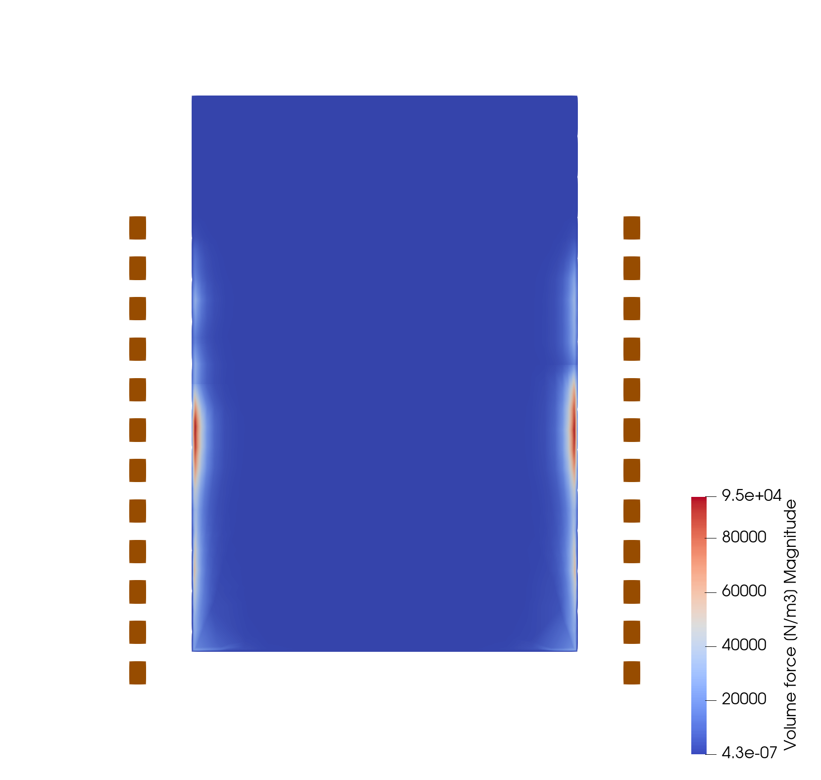
The solution explored in this use case is the application of low-frequency electromagnetic stirring using a solenoid coil to alternate magnetic fields to enable molten metal movement within the crucible. The interaction between the induced electric current in the melt and the primary magnetic field of the inductor – creates the Lorenz force, which drives the metal away from the wall of the crucible.
The system consists of a 12-turn coil placed around a cylindrical furnace containing molten iron. This coil generates an alternating electromagnetic field when an electric current is passed through it, inducing eddy currents within the molten iron, which in turn causes the liquid to move.
The system was simulated using numerical methods to evaluate how electromagnetic stirring affects the temperature distribution, fluid flow, and overall behavior of the molten metal. The geometry of the furnace and coil was modeled, and a mesh was automatically generated, with refinement in the areas of the furnace to capture detailed flow and thermal phenomena. Refinement of the mesh is mostly to capture the area of penetration of electromagnetic field, the so-called skin-effect.
Simulation process:
- Initial setup: The coil is placed asymmetrically around the cylindrical furnace, containing liquid iron at 1550°C. A current of 20 kA at 250 Hz is applied to generate the electromagnetic field.
- Fluid dynamics and thermal analysis: The electromagnetic stirring generates two distinct vortices within the molten iron, driving the mixing process. The molten iron circulates vigorously due to the electromagnetic forces, with the formation of two larger vortexes at the top and two smaller ones at the bottom, as shown in the second image. This vortex structure ensures that the molten iron is continuously circulated and mixed. They appear as four vortexes in the cross-section. Moreover, it’s important to mention that those vortices are unstable, they are dynamically growing and shrinking, making the zone between upper and lower vortices very unstable – this is what leads to efficient mixing.
- Vortex formation and mixing: In the third and fourth images, we can clearly see how the molten metal moves within the crucible. The four vortexes are created as a result of the electromagnetic forces induced by the coil. The flow is asymmetrical, with the upper vortexes being larger than the lower ones, which is due to the position of the coil, as demonstrated in the first image. These vortices contribute significantly to the mixing of the molten iron, ensuring uniform temperature distribution throughout the material.
The first image of the coil shows the setup, where the copper-colored solenoid wraps around the furnace. The second image visualizes the temperature distribution and flow of molten iron, where colors represent varying thermal states (red for hotter regions and blue/purple for cooler areas). This visualization demonstrates how the stirring effect promotes even heat transfer and mixing in the molten metal.


The third image here, a top-down view of the furnace, illustrates the vector field of the molten iron’s flow. Here, we observe the complex motion within the liquid metal, with the arrows showing the strength and direction of flow. This further demonstrates the impact of electromagnetic stirring on ensuring uniformity within the melt.

What is the result?
The result of this simulation is a well-defined and efficient stirring pattern within the molten metal, driven by the electromagnetic forces generated by the solenoid coil. The two-vortex system observed in the simulation is critical for ensuring even mixing and thermal distribution. As seen in the third image, the stirring motion efficiently circulates the molten iron, helping to avoid cold spots or temperature gradients that could negatively affect the quality of the melt.
The upper and lower vortexes in the simulation demonstrate how the electromagnetic stirring system operates within an induction crucible. The top vortexes are larger due to the positioning of the coil, and this asymmetry ensures that the molten metal is thoroughly mixed from top to bottom. This process is essential for preventing the formation of hot or cold zones within the molten iron, ensuring uniform temperature and composition throughout the melt.
Why is this simulation useful for engineers?
This simulation gives valuable insights into the dynamics of electromagnetic stirring in induction furnaces. By modeling the fluid flow and thermal distribution, engineers can predict the behavior of molten metal in real-world processes, optimizing furnace design, coil positioning, and operational parameters to achieve the best possible results in metal melting and alloying.
- Optimization of furnace design: The simulation provides engineers with a tool to understand how different geometries and positions of coils and operating frequencies impact the fluid motion and temperature uniformity in the crucible. This is crucial for designing furnaces that can handle different types of metals and achieve consistent results.
- Efficiency in industrial applications: By using electromagnetic stirring, engineers can replace mechanical stirring systems that may be impractical or less efficient for high-temperature applications. This non-contact stirring method ensures that the molten metal is properly mixed, reducing defects in the final product.
- Improved product quality: With better control over the mixing and temperature distribution, the overall quality of the molten metal improves, leading to fewer impurities, more consistent alloying, and better final material properties.
