Induction brazing simulation: case study
Induction brazing is a process that joins metals using a filler material with a lower melting point, seamlessly bonding materials like brass, copper, steel, and aluminum. The process demands precision—every joint needs strength equal to or greater than the base materials to ensure durability and safety.
For engineers in industries like aerospace, power plants, and oil refineries, quality is extremely important, but so is efficiency. Every cycle must hit the right temperature with minimal distortion, stress, or oxidation.
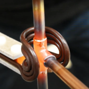
We can see a simple induction brazing process on the following video.
In the following case study, we analyze the simple simulation setup to find out how engineers can use simulation software to optimize the induction brazing processes.
What is the challenge?
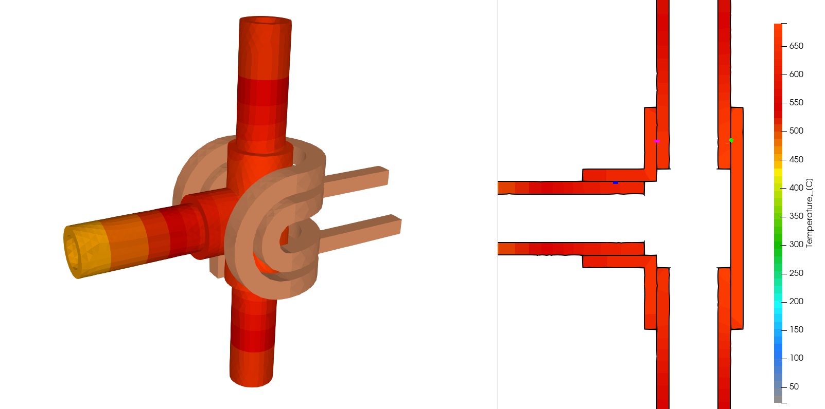
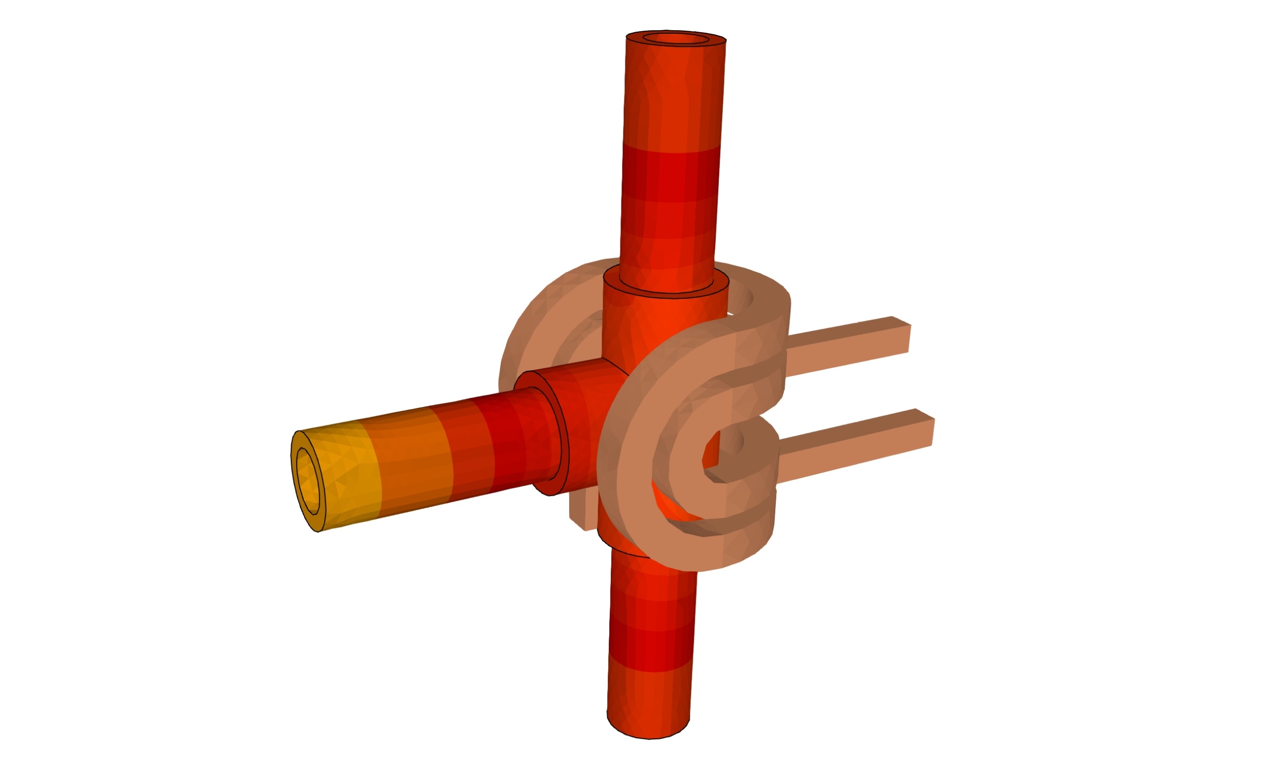
Induction brazing, as seen in the images, is a precise yet challenging process. The simulation reveals complex pipe geometries and joint areas that demand selective heating to avoid unnecessary stress and distortion.
In these simulations, the red and orange gradients represent the temperature distribution across the parts. Achieving an even temperature across these shapes, especially where metals meet, is a challenge. Each joint requires consistent heat application without overheating, which can lead to joint weakness or material damage.
For engineers, managing temperature distribution effectively is very important. As shown, the electromagnetic fields concentrate around the joints, indicating the need for precise control to avoid overheating specific areas while ensuring sufficient heat in the joints.
Without accurate predictions, manufacturers risk uneven heating, leading to weaker joints, increased oxidation, and compromised durability, which is particularly problematic in sectors demanding high reliability.
What is the solution?
CENOS simulation software offers engineers a detailed visual and analytical approach to optimizing induction brazing processes. The simulation images and animations provide insights into temperature distribution, coil positioning, and heat transfer efficiency, helping engineers make informed adjustments before physical implementation.
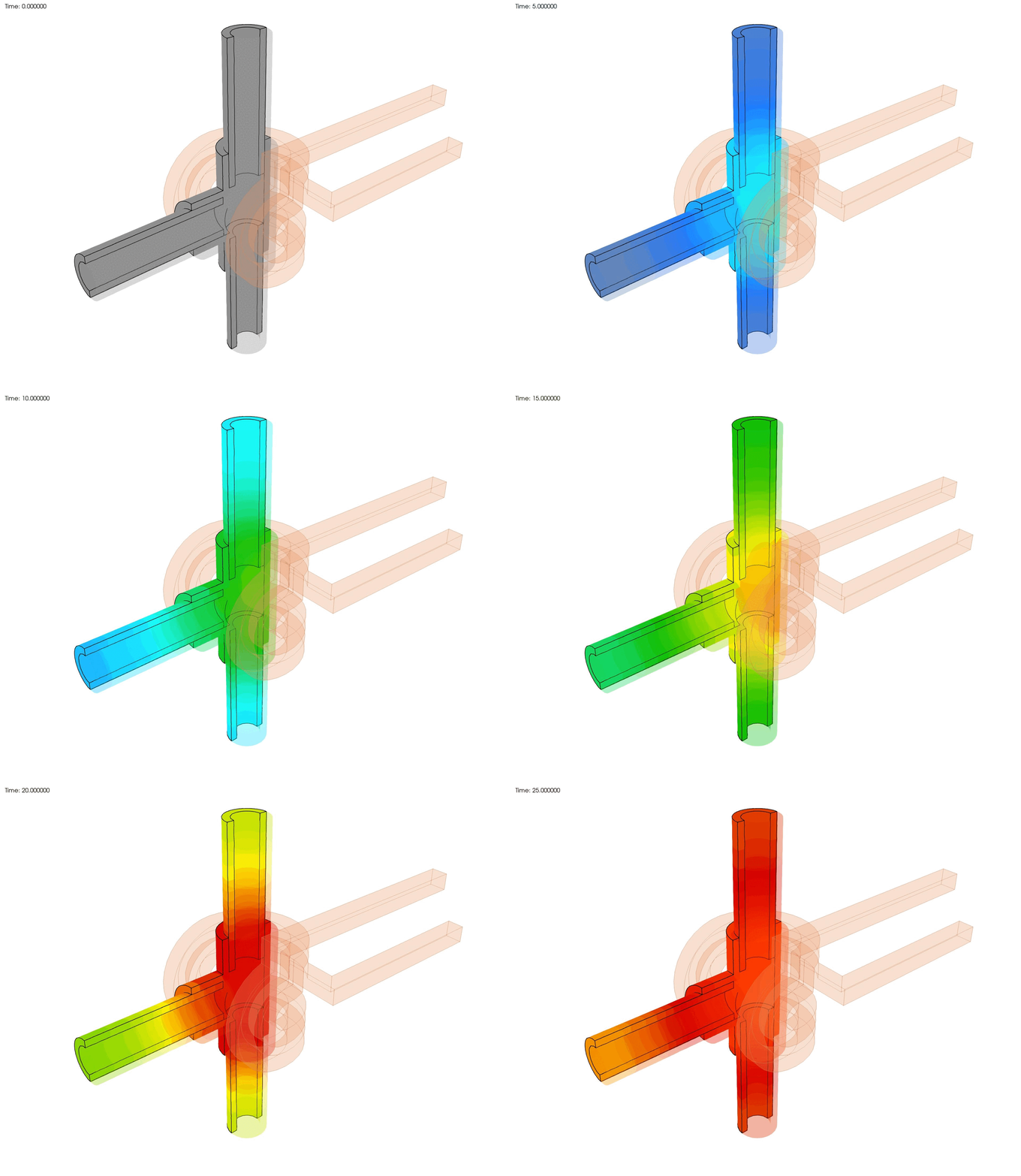
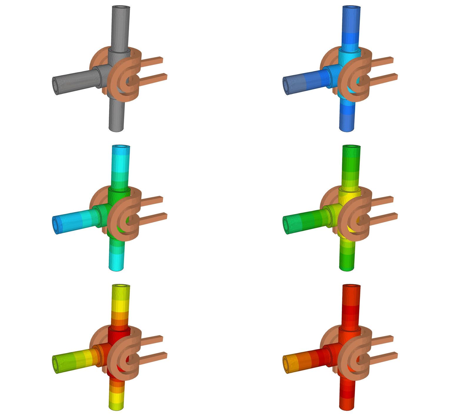
The gray parts represent the metallic components to be brazed, while the copper-colored coils show the induction heating elements. At the initial stage (seen in the zero-time frame), there is no heat distribution, indicating the setup just before the current flows through the induction coils. This clear starting point allows engineers to visualize the base setup without any thermal effect, setting a benchmark for temperature mapping.
As the simulation progresses, temperature gradients appear across the metallic parts, represented by a color scale from gray to bright red. Red zones indicate higher temperatures, while cooler tones such as gray and yellow represent lower temperatures.
This color-coded temperature distribution enables engineers to see how heat goes through the parts over time, allowing them to confirm whether the targeted areas are reaching optimal brazing temperatures without overheating other regions.
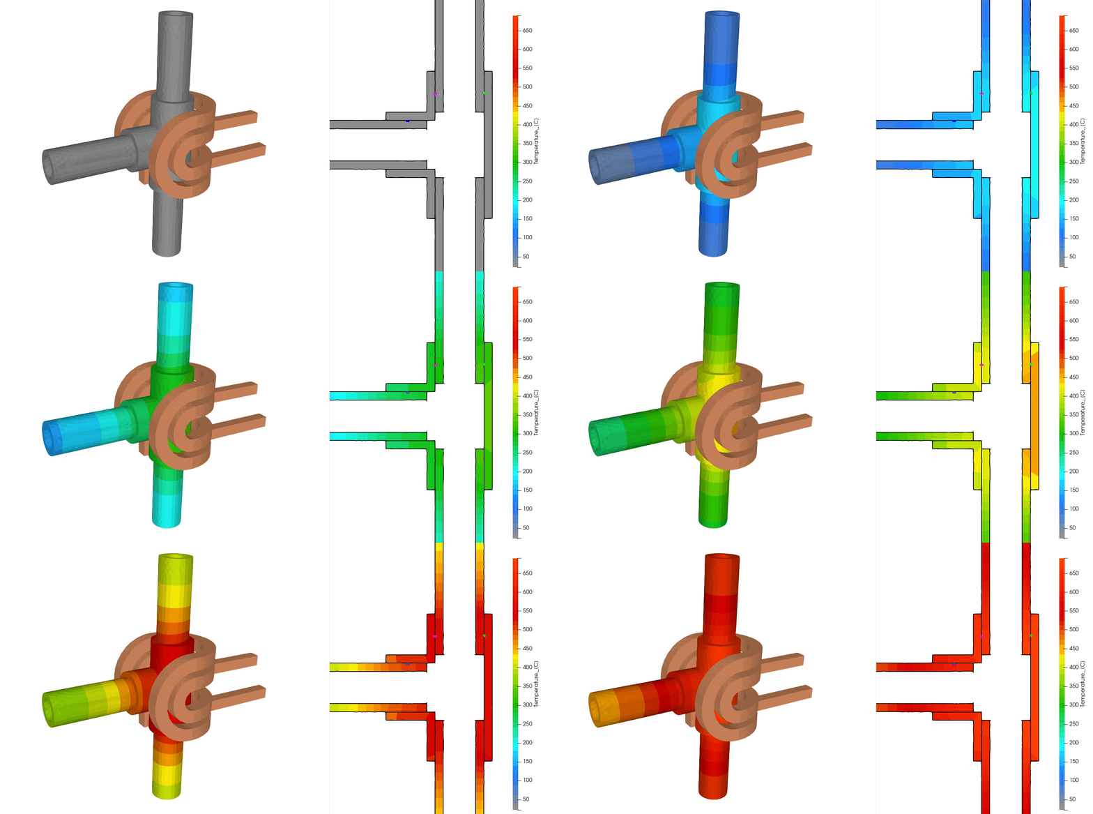
In the animation, engineers can observe the dynamics of heat transfer in real-time. The heating process highlights how temperature gradually accumulates in the joints, providing clear visual feedback on how well the coil design and power settings are performing.
Engineers can identify areas where adjustments are needed, such as modifying coil positions or tweaking power levels, to guarantee uniform heating across complex geometries.
This simulation allows engineers to address potential heating inconsistencies and optimize coil design. By understanding where the coils need to focus energy, engineers can refine the coil configuration to maximize energy efficiency, reduce power consumption, and ensure precise, selective heating.
For instance, if certain areas are heating faster than others, engineers can adjust the coil design in the software to decrease heating in these hotspots, achieving a balanced temperature profile throughout the part.
In summary, the images and animations provided by CENOS allow engineers to:
- Visualize and validate heat distribution across the designs.
- Identify and correct any heating imbalances before production.
- Optimize coil design and power settings to achieve energy-efficient, precise heating.
- Predict potential issues like uneven heating or overheating in sensitive areas.
Magnetic field visualization
These images provide a view of the magnetic field around the induction brazing setup. These visualizations reveal the magnetic flux lines generated by the alternating current passing through the induction coil, which plays an important role in heating the target areas.
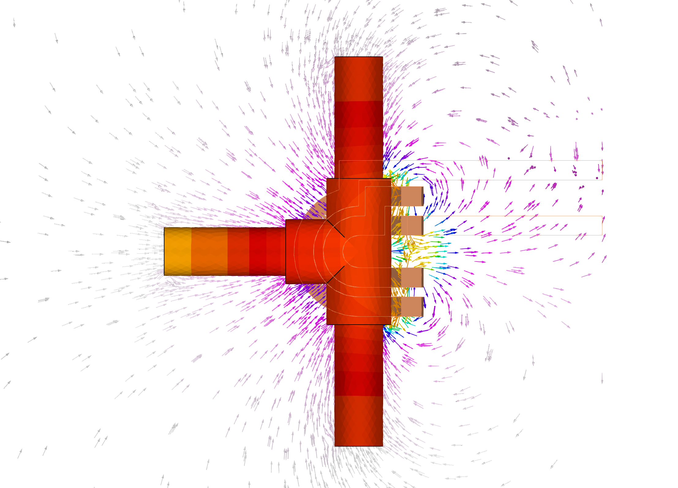
In the first image, the flux lines are shown radiating around the setup, concentrated near the joints and coils. Engineers can observe the intensity and spread of the magnetic field, as indicated by the density and color gradients of the flux lines.
This information is valuable because it allows engineers to see precisely where the electromagnetic energy is strongest, making sure that the heat generation aligns with the desired brazing zones. If certain areas appear underpowered or overheated, engineers can adjust the coil design or placement to achieve a more balanced magnetic field distribution.
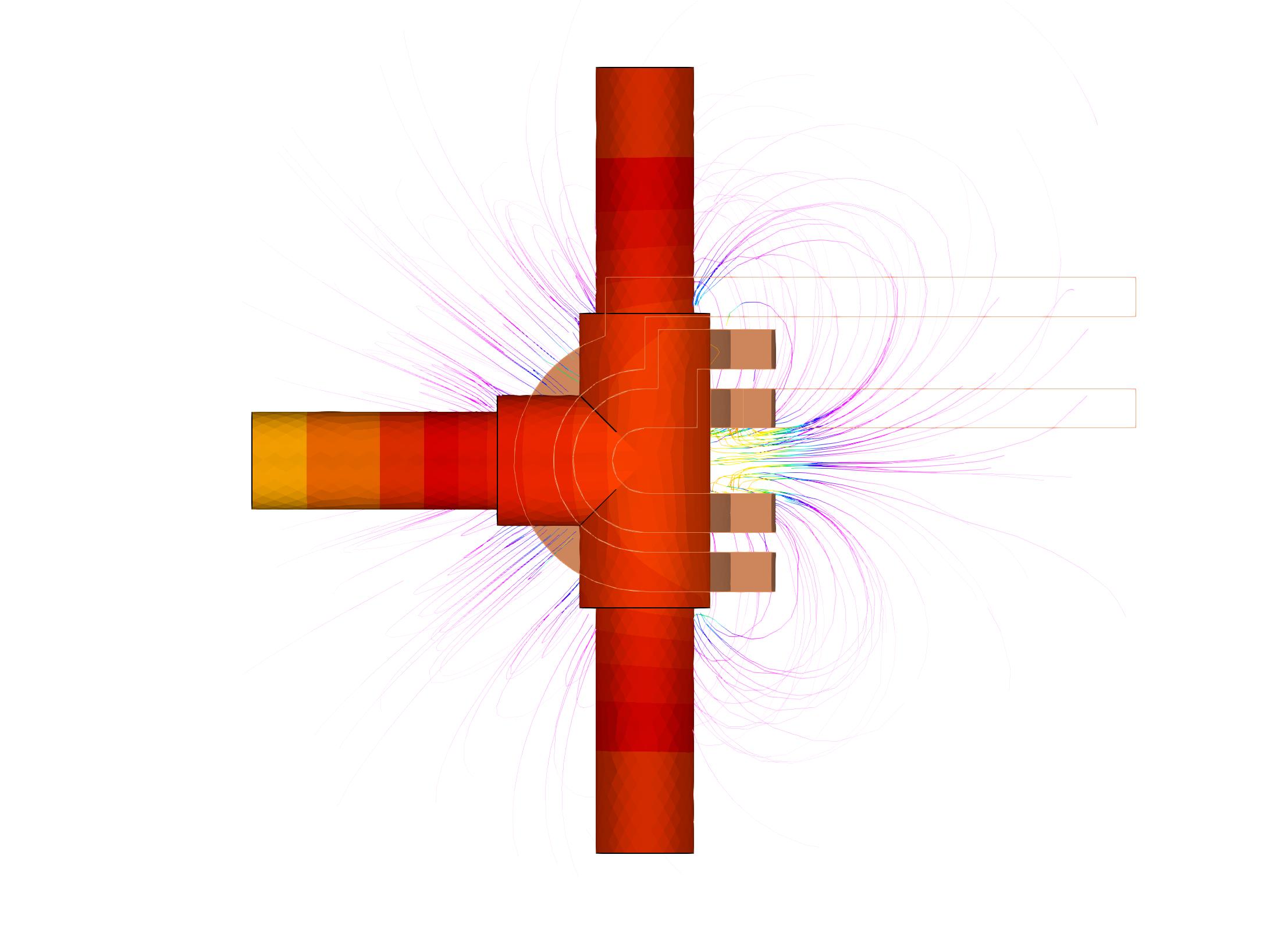
The second image focuses on a similar setup, with flux lines drawn more tightly around the joints. The colors in these flux lines indicate the field’s strength and direction, allowing engineers to understand the exact path of energy flow around the brazing area.
This is important for identifying areas where magnetic leakage may occur or where additional coils or power adjustments may be required to maintain uniform heating.
By analyzing these magnetic field visualizations, engineers can:
- Optimize coil positioning for focused and efficient energy delivery to the brazing joints.
- Identify potential field imbalances that might lead to uneven heating, which can compromise joint quality.
- Adjust power settings and coil configurations based on visual feedback, ensuring that only the targeted areas reach the desired temperature without excess energy wastage.
What is the result?
In the competitive landscape of manufacturing, precision isn’t just a preference, but it’s a necessity. Engineers using CENOS for induction brazing find that simulation helps to solve the demands of modern brazing challenges.
By eliminating guesswork and optimizing setups digitally, simulation software accelerates production timelines and reduces material waste. This process strengthens quality control and maximizes reproducibility, which are important for industries like aerospace, automotive and power generation, where reliability is non-negotiable.
Simulation allows engineers to move quickly from concept to production, improving designs and troubleshooting virtually, long before manufacturing begins. For companies, this means not only faster production and lower costs but also the competitive advantage of delivering a more reliable product.

