What makes a good CAD geometry
The geometrical model of your system plays a big role in how easy or hard it will be to set up and get accurate results from a wireless charging simulation.
We have summarized the main aspects for good, simulation-friendly CAD file, which should be followed in order to create a simple, trouble-free geometry for your simulation.
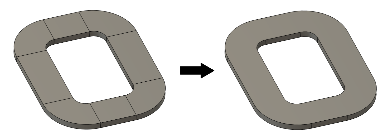
Create geometry as a single solid
In many CAD softwares it is easier to build the coil or other part geometries from blocks, which are then combined to form a complete object CAD. When creating geometry for simulation, these blocks must be fused together to form a single solid – doing this helps remove unnecessary faces between blocks and simplifies setting up geometric properties, but the meshing process as well.
Simplify geometry
Computer simulation starts with a geometrical model of the real life problem – you need to accurately depict the geometry to precisely calculate the physical aspects of the model. However, in most cases you can disregard some of the geometrical details, which do not have such a significant impact on the physical results, to optimize the simulation.
The following features can be deleted, as they take up significant amount of calculation time and computer power without considerable contribution to results.
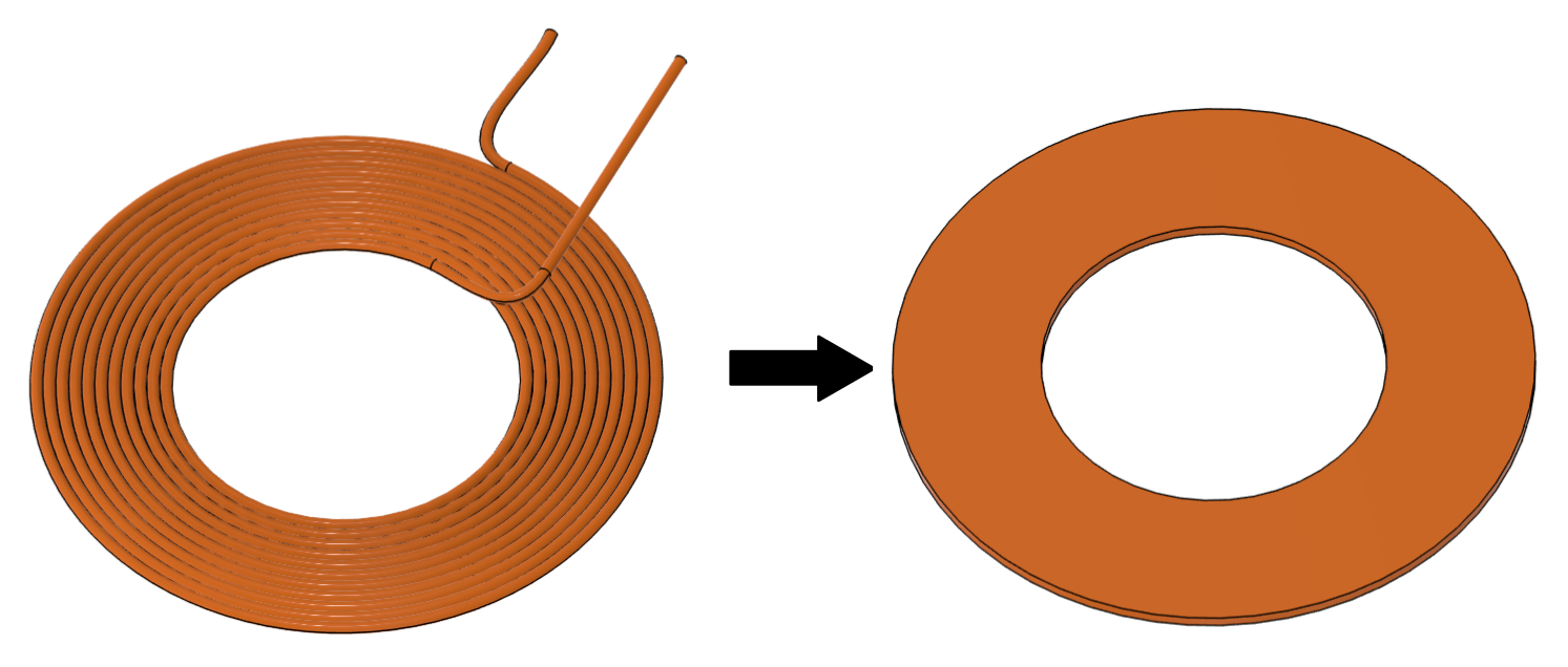
Simplify stranded coils
For simulation purposes we don’t need to have every strand resolved in the geometry. To make things simpler, replace your detailed coil CAD with a simplified, solid volume!
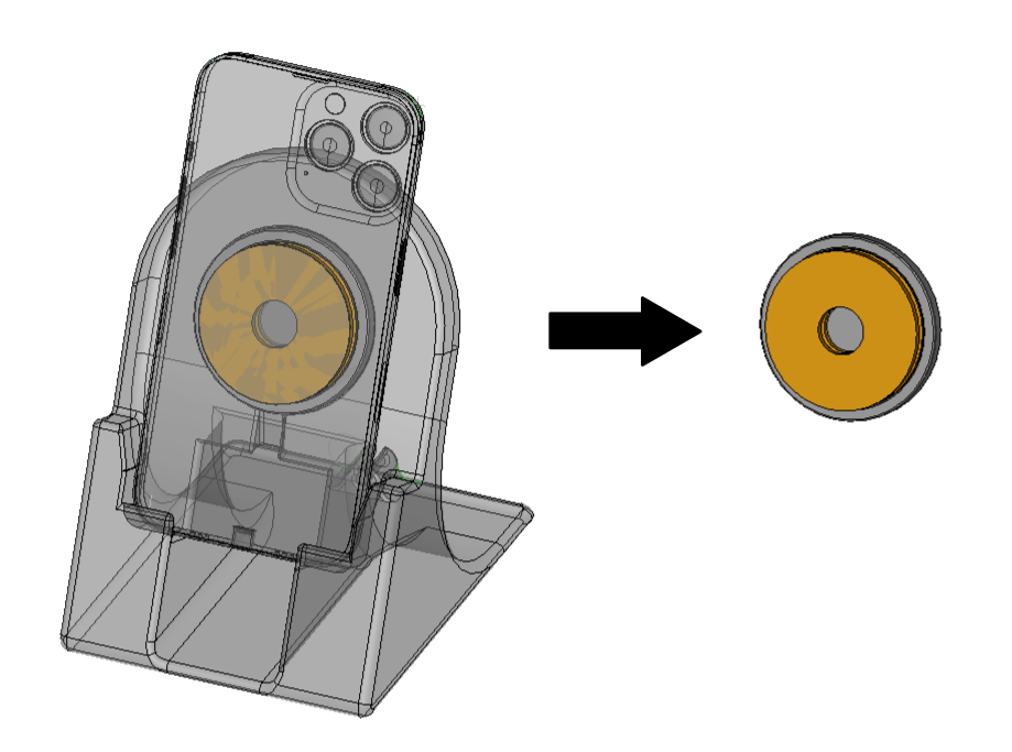
Delete unnecessary elements
System elements such as plastic structural parts or connections with outer elements can be deleted.
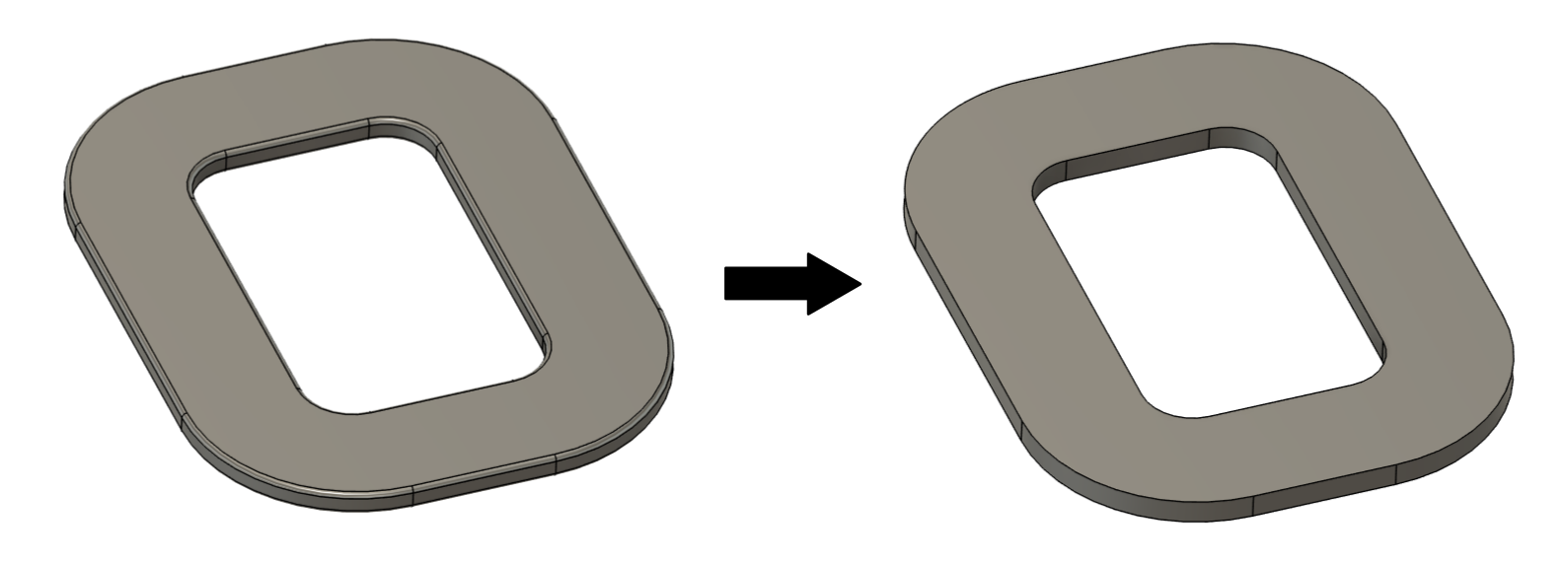
Get rid of small details
Small details have a negligible impact on the simulation results, but they take up a lot of calculation time, as they need to be resolved through mesh, which increases the mesh element count significantly. Get rid of details such as small fillets, holes and narrow gaps in coils, ferrites etc.
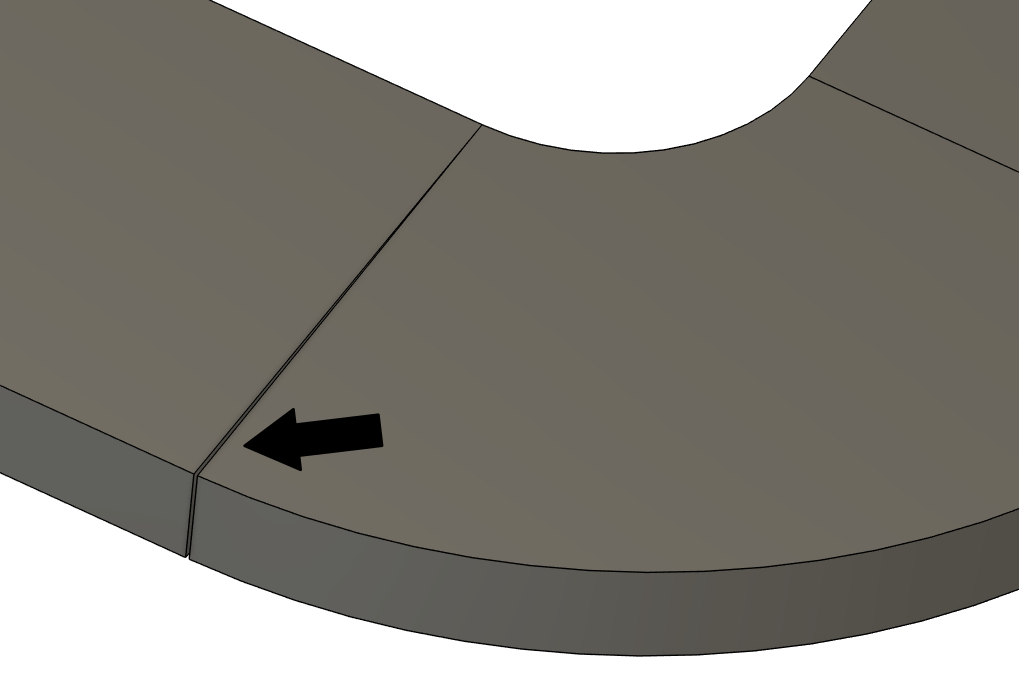
Resolve inaccurately connected geometrical parts
During geometry creation be careful with connections between different parts – inaccurate connections will result in meshing problems and calculation errors!
Overlapping
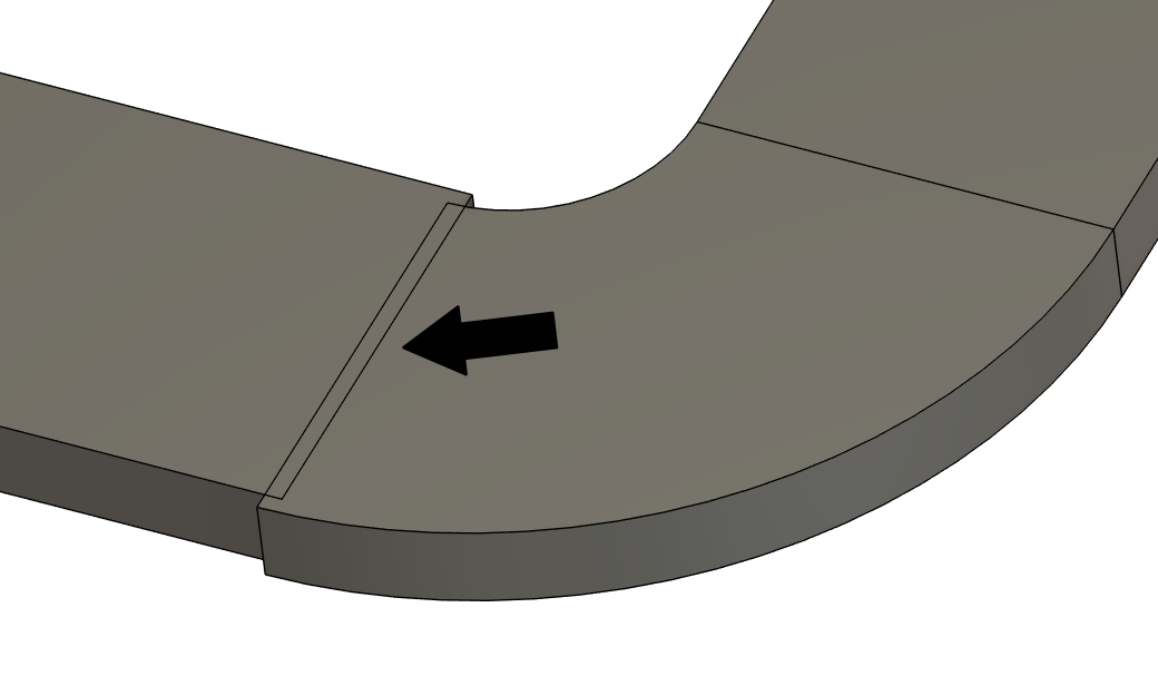
Gaps
If you follow these tips for achieving good CAD, you will have a geometry which will be easy to manipulate and mesh, and fast to calculate!
