Thermal analysis for inductor cooling and fluxes
In this article we will learn how to setup inductor and flux concentrator thermal definition for calculation of heating and cooling.
Geometry role setup
When defining geometry roles, you need to specify additional roles for such simulations. You need to group faces from:
- Flux surface
- Inductor outer surface
- Inductor inner surface
To do this, in geometry role section you need to select the role Other and choose all of the faces that correspond to it.
Physics setup
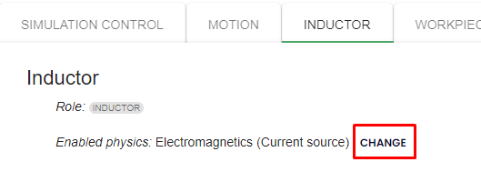
In the physics section you need to enable thermal analysis for inductor and flux concentrator.
To do this, click change on top of the page and check thermal analysis.
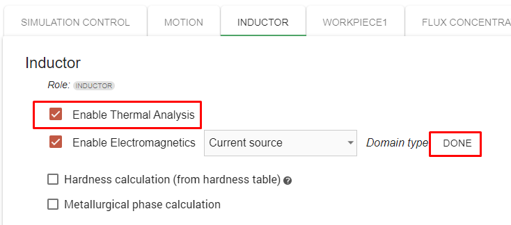
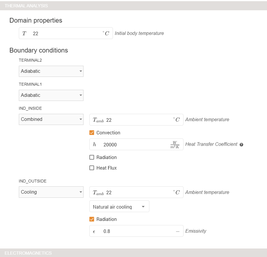
When this is done, you will see a THERMAL ANALYSIS section appear where you need to specify the boundary conditions.
For the inductor assign:
- terminals as adiabatic;
- outer surface as natural air cooling;
- inner surface as combined where you input Heat Transfer Coefficient as around 20000.
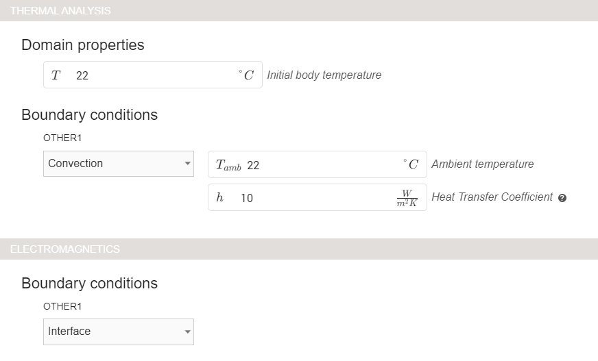
For electromagnetics assign ground and power/current/voltage as usual, but assign interface to the surfaces.

For the flux concentrator assign convection as the thermal boundary condition and interface as the electromagnetic boundary condition:
Now you have setup the physical conditions to simulate inductor cooling and flux heating.
All the other parameters can be setup as usual, and you can click RUN to simulate the case.
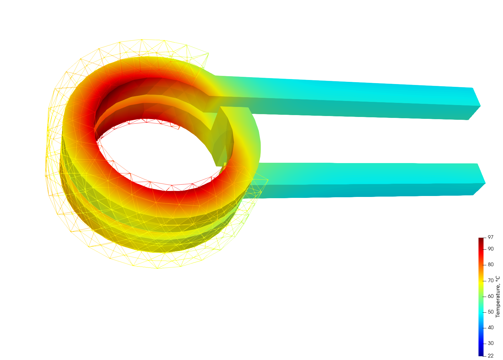
In results you will be able to see temperature for inductor and flux concentrators.