Sliced case tutorial
In this article we are going to learn how to build a simple gear sprocket hardening case using symmetry approach in CENOS Induction Heating simulation software.
Sliced cases are cases where only a part of a full 3D geometry is being used for the simulation. This offers faster calculation, without losing accuracy.
Prepare your geometry
Geometry is the beginning and a cornerstone of every simulation, so we need to start by preparing our geometry for the simulation.
Prepare CAD files
First you need to make sure that your CAD files have been created correctly:
- Make sure that the whole geometry has been cut at the same plane (the black lines in the image below) – even small deviations of the geometry from the cut plane can lead to problems during setup or calculation;
- We suggest centering the geometry around one of the axis (X, Y or Z), since it will help with result visualization later on. However, it is not mandatory;
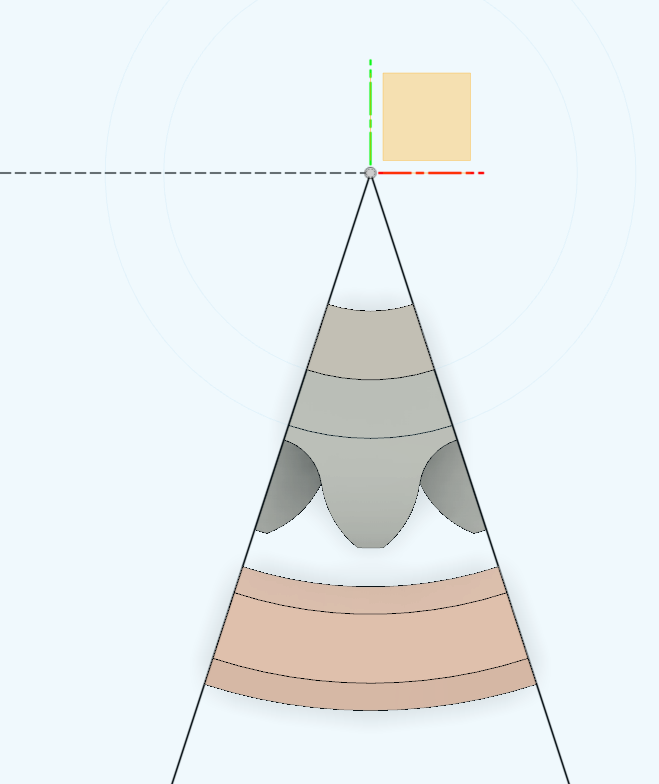
- If you choose to add your own air box as well, make sure that the previous points are true as well – it is cut on the same plane (black lines in the picture) and is centered around one of the axis.
Once the geometry is prepared, we can move on to case setup.
Import CAD files
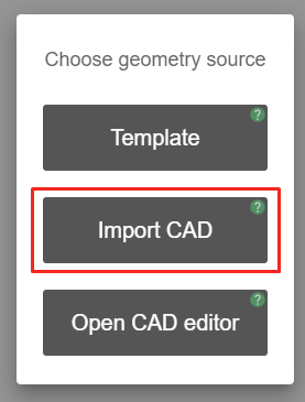
Since we have created our own CAD files, we need to select the geometry creation approach. In CENOS home window click Import CAD.
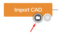
Click the blinking Folder icon to select the CAD files you want to import.
Select STEP files of your system and click Open to import them into CENOS.
Generate air box
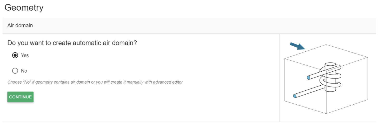
Once the CAD files are uploaded, CENOS will ask if you want to automatically generate the air box (ambient environment around your system). Click Yes on the choice, and then CONTINUE.
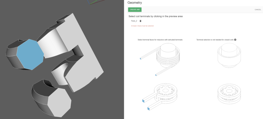
Select your inductor terminals – for a slice case those are the inductor faces where the geometry has been cut.
In this case, since the full inductor had 2 windings and has been cut, we can select either all 4 faces, or only 2 faces – both cut faces for one of the windings:
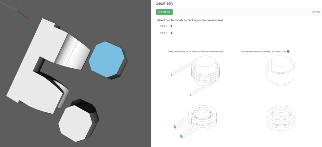
Select the other side as well and click CREATE AIR to automatically generate the air box!
Define groups
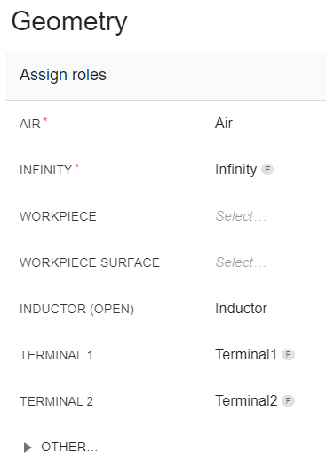
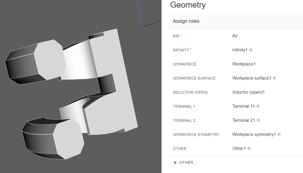
Once the air box is generated, you will be redirected to the group creation window. Here you will see a list of groups you need to define for your system, such as which one is the workpiece, where are inductor terminals etc.
You will see that the selected inductor and its terminals have already been assigned automatically, so we need to assign roles to the other inductor and its terminals as well as to the workpiece and its surface.
Inductor
First, to group both inductor windings as one inductor, we need to select the terminal1 group and choose the same side face of the other winding.
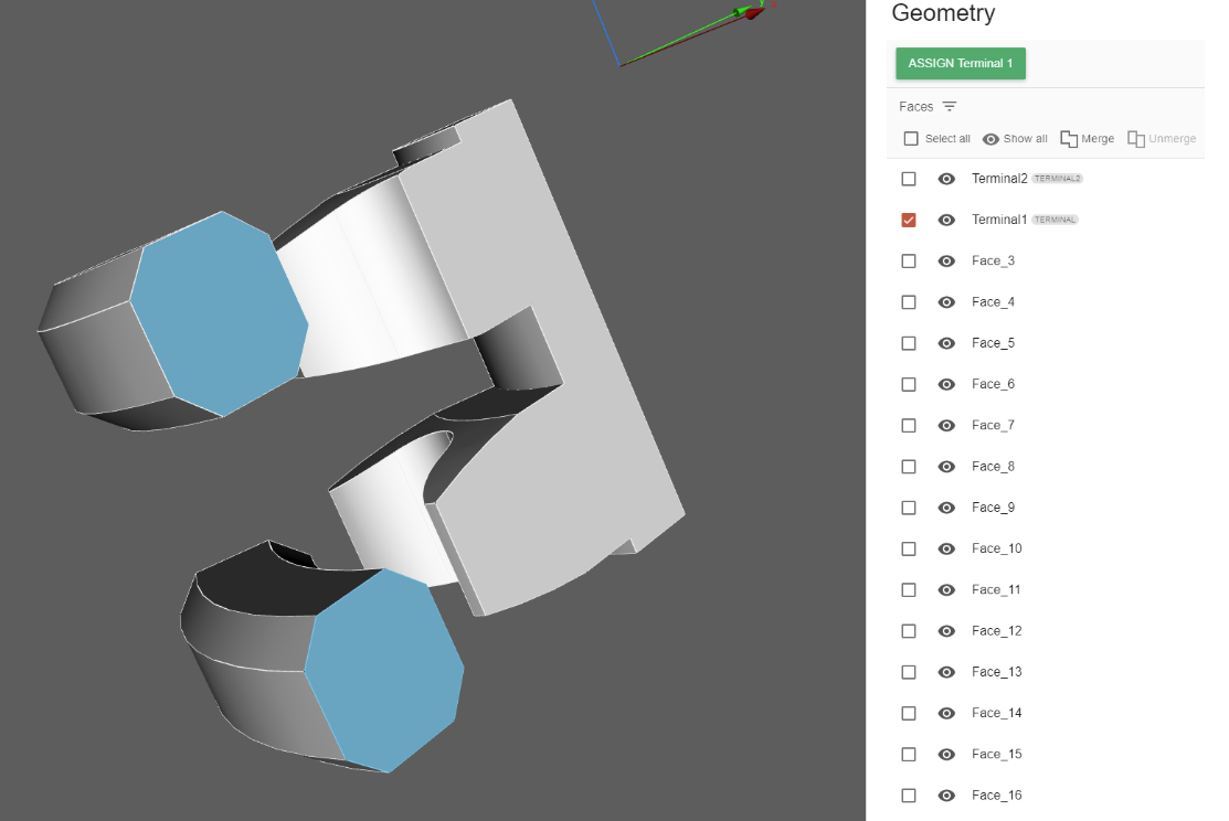
Click ASSIGN Terminal 1. CENOS will ask if you want to re-assign a role, since one of the faces already had a role of Terminal 1, click re-assign.
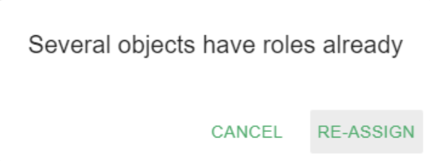
After that, do the same thing for Terminal 2, and for Inductor – select the other winding as well.
Before it was mentioned that you could also select all four cut plane faces when generating the air box – in this case each inductor winding would be its own inductor group – this will not change anything more than the fact that you would need to input the power value twice – once for each inductor group.
Once that is done, we can move on to the workpiece.
Workpiece
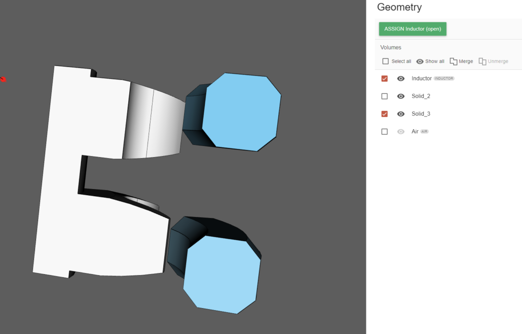
Select the group (in this example, WORKPIECE), select the corresponding volume from the list or directly from the screen, and click ASSIGN Workpiece.
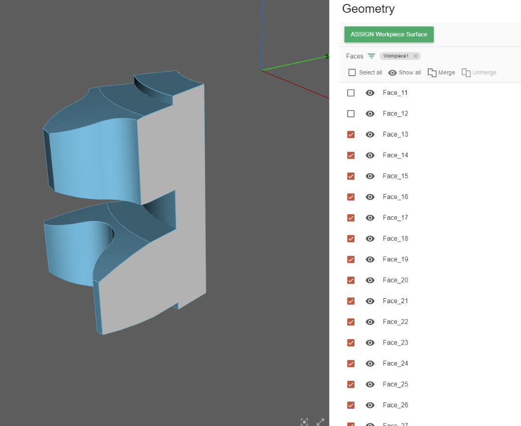
Next we need to define the workpiece surface group. Here we do the same – select the group WORKPIECE SURFACE, after that select the corresponding faces.
You can filter the faces by the workpiece and click Select All to ease the process. However, note that since this is a slice case – so it is only a fragment of a full 3D geometry – the workpiece surface does not include the two faces that are on the cut planes. We need to deselect those faces, which we can do by holding shift and clicking on the two faces in the geometry preview.
You can see that two faces have not been selected (you can see one of the faces in the preview window). After this, click ASSIGN Workpiece Surface.
The two unselected workpiece faces can be also grouped together as they will have the same properties, so we will not need to input the same properties two times.
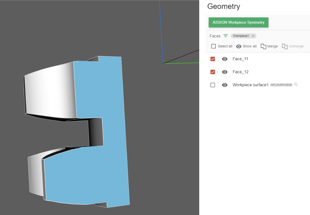
Under all of the assigned roles, you can see a dropdown menu OTHER… – here choose the option Workpiece symmetry.
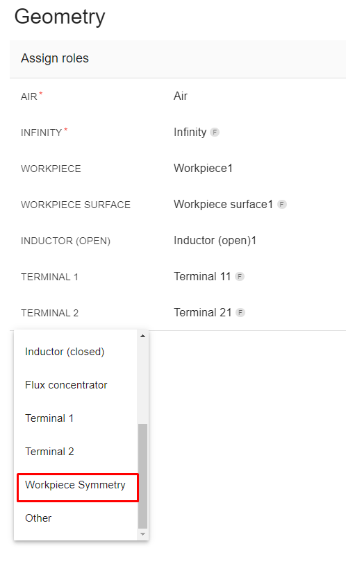
In the selection menu select the two faces and click ASSIGN Workpiece Symmetry.
Modify Air
Next, since this is a slice case, we need to modify the air box roles as well. Go to the INFINITY group and click UNMERGE.
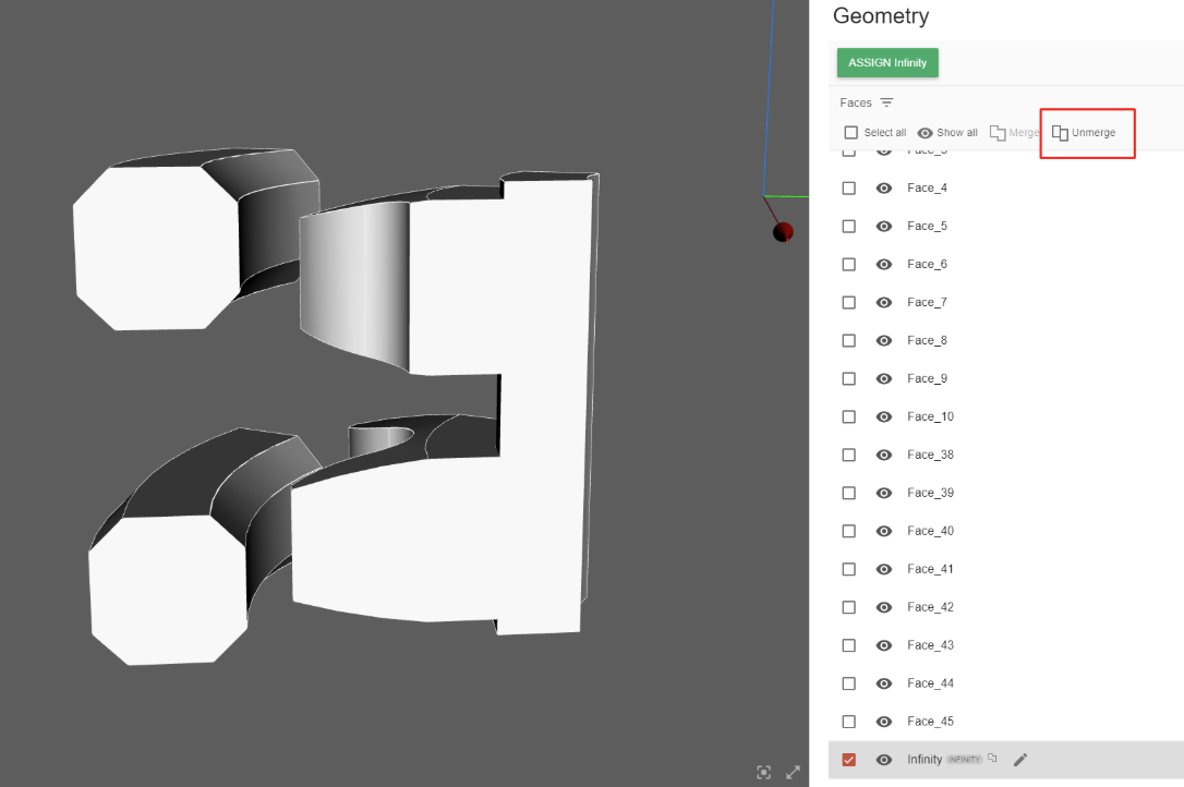
In the popup window click REMOVE ROLE AND UN-MERGE.

Next, go to INFINITY role again and select the three air faces that are not on the cut plane. All three of them will be selected together.
Click ASSIGN Infinity.
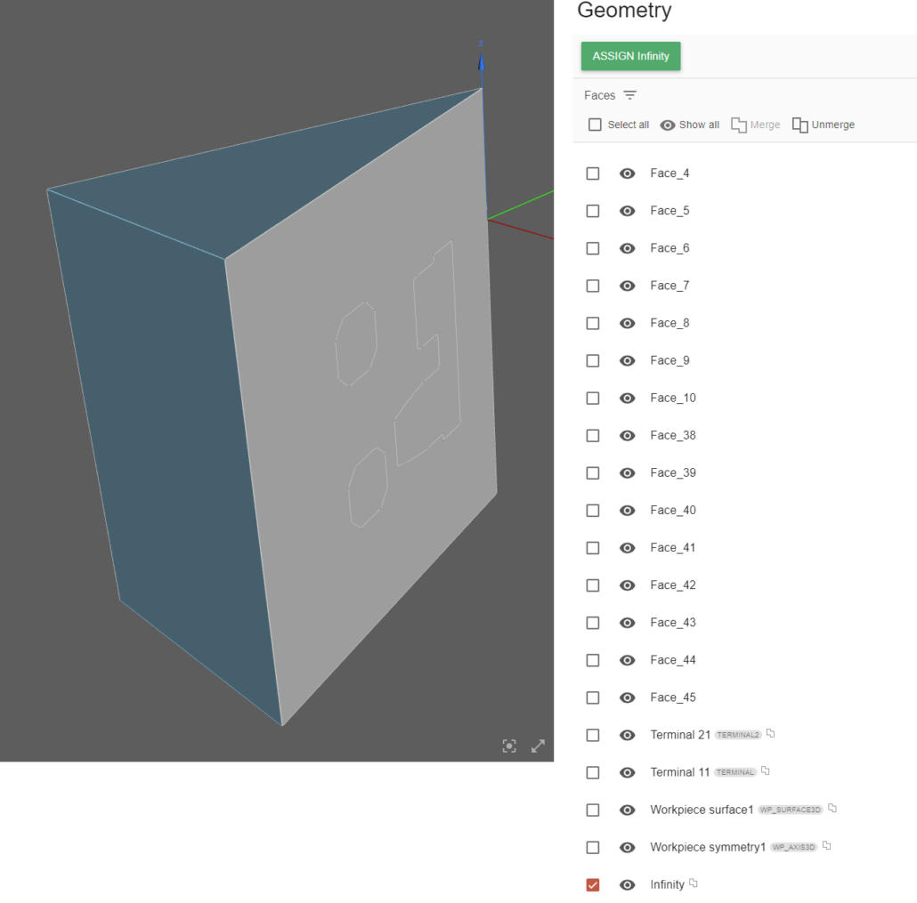
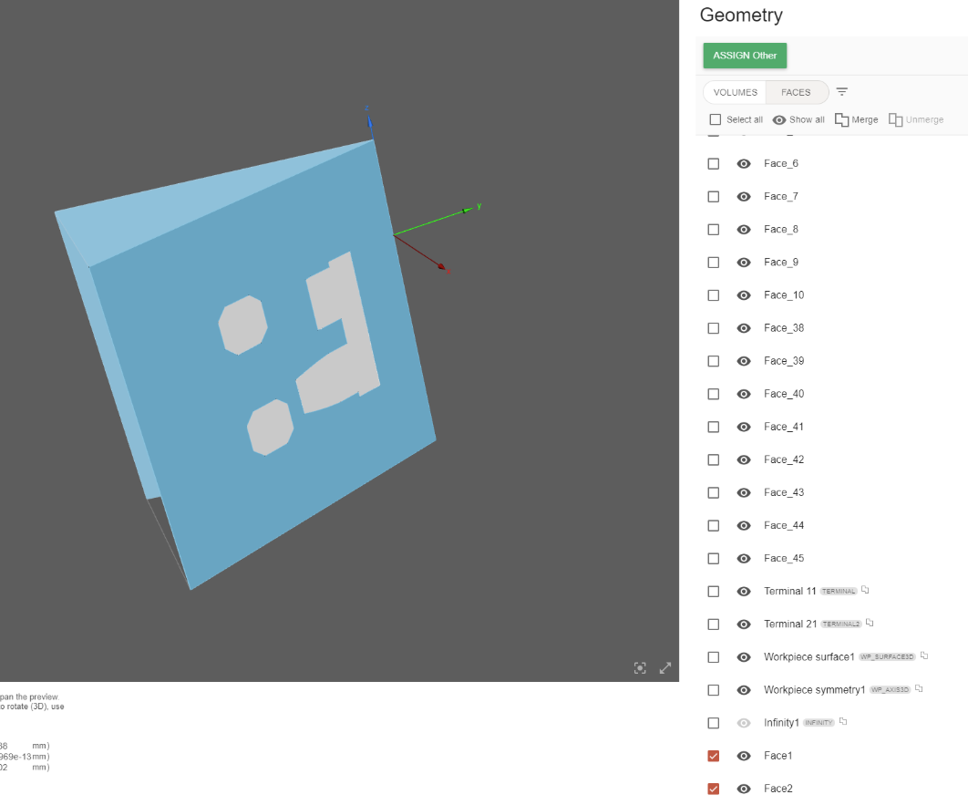
And for the other two faces that are on the cut plane, do the same thing as for the workpiece – this time choose Other and assign the role.
Now all of the geometry roles and groups have been created!
Once ready, click GO TO PHYSICS for Physics definition!
Define physics
You will be redirected to the Physics window, where physical definitions are present. On the left you can see the preview window of your geometry, but on the right – the actual physical definitions. You can navigate physics through the domain tabs above the physical definitions.
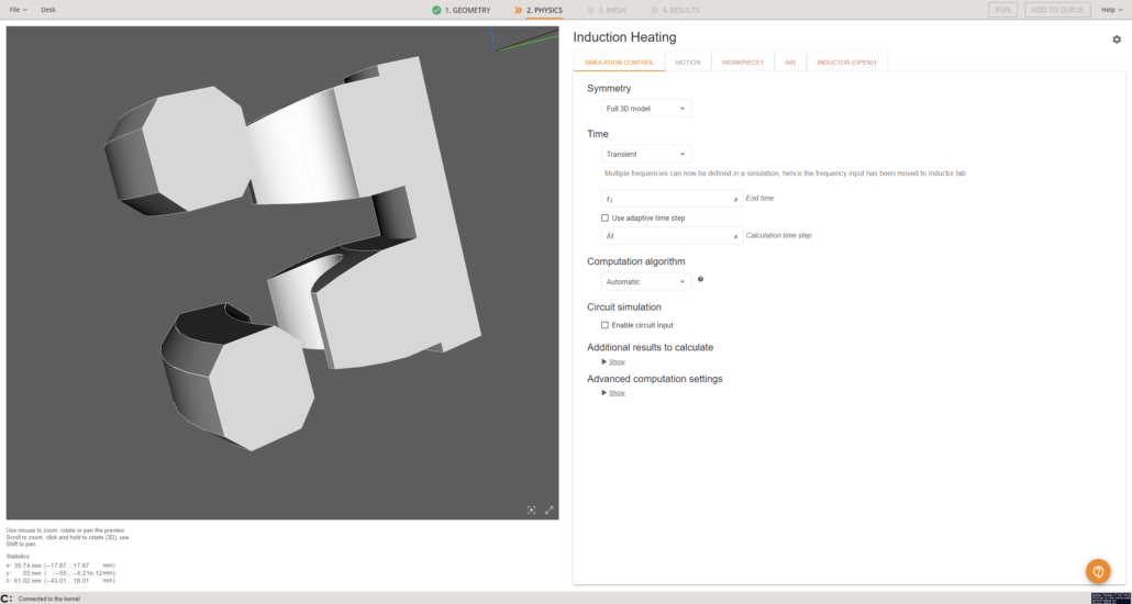
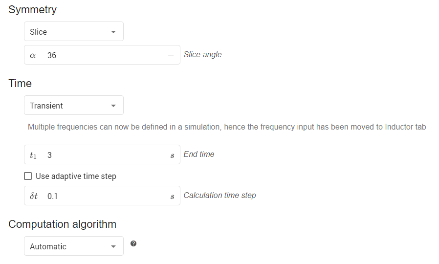
Simulation control
In the SIMULATION CONTROL window define the simulation as a slice of 36 degrees, transient, 3 s End time and 0.1 s time step. For Computation algorithm leave Automatic.
Gear
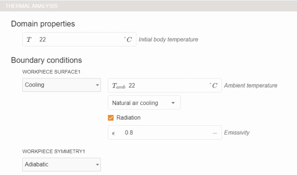
Select WORKPIECE1 from Domain bar. For Material click SELECT… and choose Medium Carbon Steel 1045 (B(H), t depend).

Under THERMAL ANALYSIS leave everything as it has been automatically assigned.
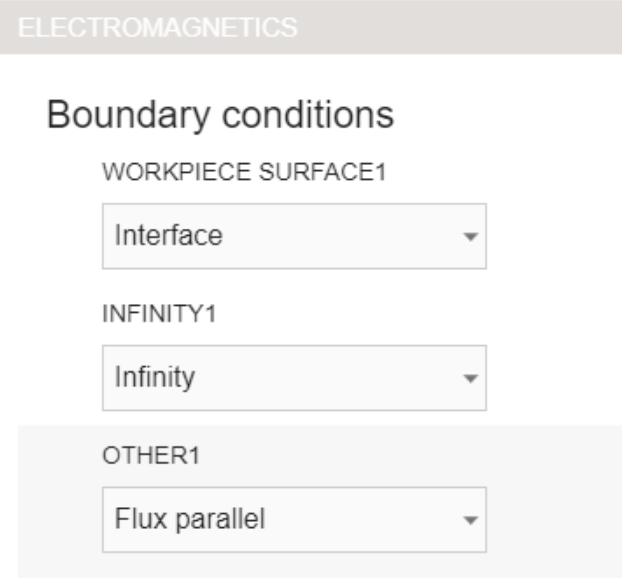
Under ELECTROMAGNETICS you will see that the symmetry boundary conditions have been assigned automatically as well.
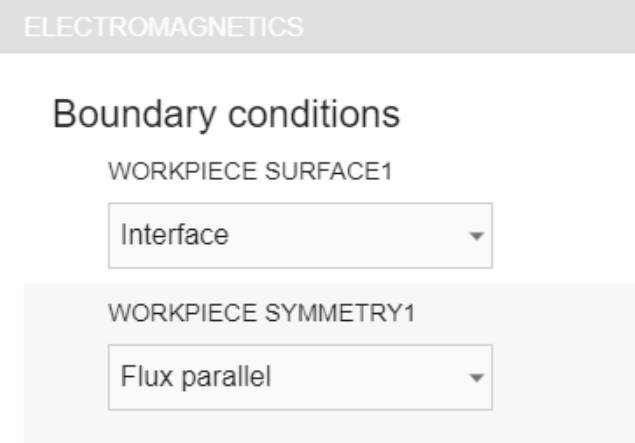
To learn more about setting Boundary conditions, please refer to this documentation article
Inductor
Switch to INDUCTOR in Domain bar. You will see that the material has been automatically assigned.

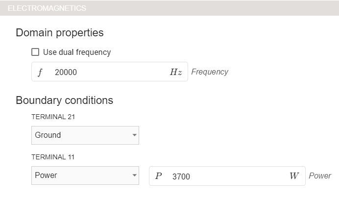
Under ELECTROMAGNETICS input 20 kHz frequency, choose Power for TERMINAL11, Ground for TERMINAL21.
The full 3D case would have power of 37000 W, however, this case only has one tenth of the whole geometry, so the power has to be divided accordingly. You can read more about managing inductor inputs in this documentation article
So here we input 37000 * 36 / 360 = 3700 W
Air
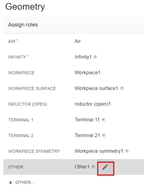
Switch to AIR tab. You will see that under ELECTROMAGNETICS the role OTHER1 does not have the boundary conditions set. Set it as Flux parallel, the same as for the workpiece.
You can read more about setting boundary conditions in this documentation article
With this all of the physics parameters have been defined and you can click RUN to save and run the case!
Evaluate results
In the end of the calculation our results viewer will automatically open with a pre-set temperature state, and you will be able to see the temperature field distribution in the workpiece in the last time step.
Results can be further manipulated by using CENOS Results Viewer.
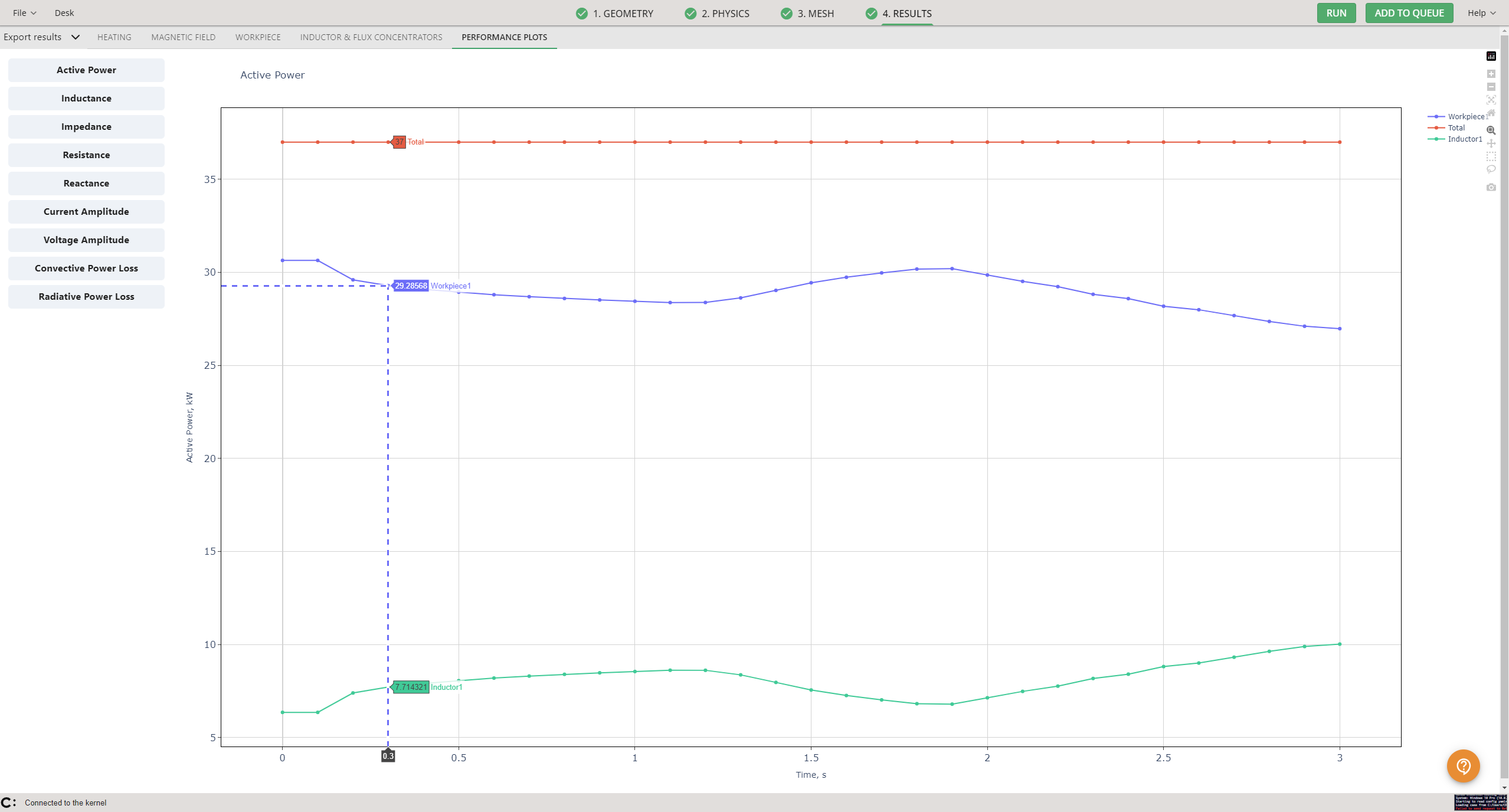
In results, sliced cases have one exception to usual results – in the performance plots tab you will see that the active power has been calculated to represent the total power for the whole system – as mentioned before, the full system would have 37 000 watts.