Port definitions in CENOS
An essential element of your RF simulation is the port and it is important to figure out how to define it properly. For most applications, you won’t need to modify your geometry to feed your model, as defining a port in CENOS : RF has been made incredibly straightforward and can be done with your existing geometry.
Currently there are two types of port definitions in CENOS:
- Discrete port
- Coaxial port
Discrete port
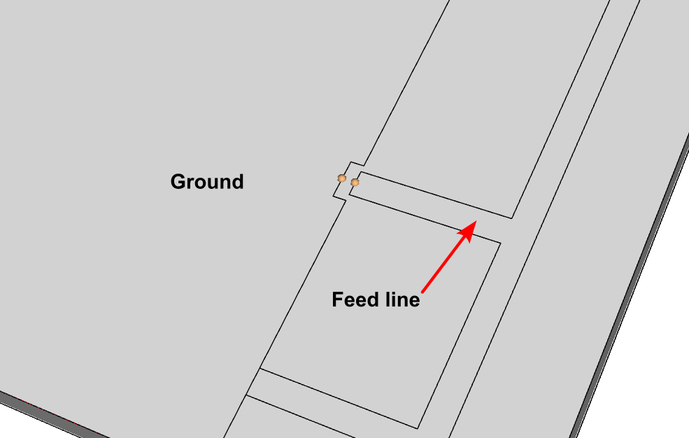
The discrete port in CENOS is the simplest way to define the feed of your model. Essentially, all you have to do is to select two terminals – one on each conductive surface where you connect the feed in real life. The placement of each of the terminals is dependent on the type of model you are simulating.
For example, if you are simulating a simple microstrip antenna, such as an IFA, you would place one terminal on the edge of the feed line of the microstrip and the other on the closest edge of the ground plane.
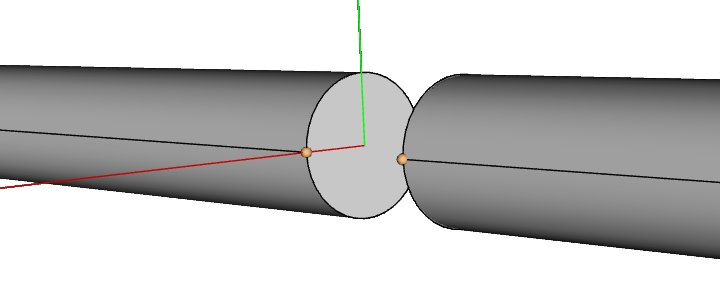
If you are simulating a symmetrical design, such as a dipole antenna, you would have to place a point on each pole, leaving a gap in between the poles.
Impedance settings
When using a discrete port you can define several of its parameters in the Physics section, one of them is the complex part of the impedance, which can be configured as reactance or frequency-dependent capacitance.
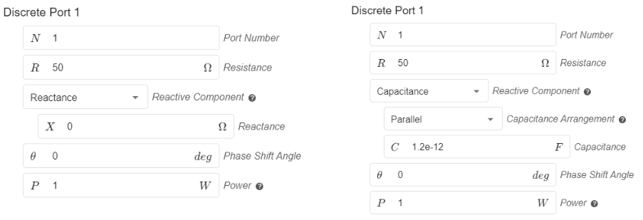
You can also define the input power, as well as the phase shift angle when using multiple ports.
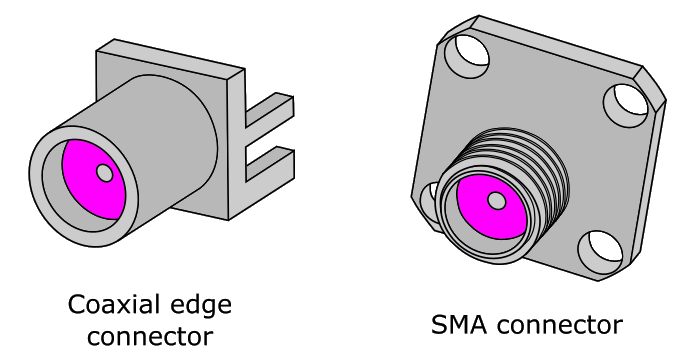
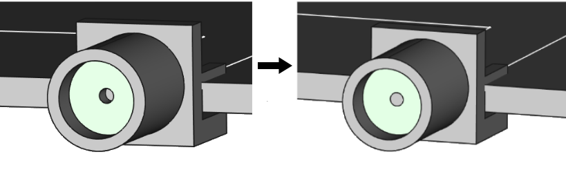
Coaxial port
Coaxial ports are ports where the connection surface is made by a coaxial connector or cable. If your model already contains the geometry for the cable or connector, all you have to do is to select the surface of the dielectric to define such a port.
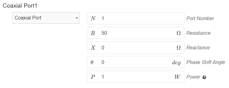
Impedance settings
Within the Physics section, in the PORTS tab you can easily modify the input impedance, phase shift angle and input power.
Here is a quick video tutorial on setting up a coaxial port and its necessary roles:
Limitations
Although the process of defining a port in CENOS : RF is incredibly straightforward, there are a few things to keep in mind.
Discrete port terminal selection
Currently, the possible points of terminal selection are fixed. On a straight edge, you will be able to place a terminal on its leftmost and rightmost point and in the middle of these two points.
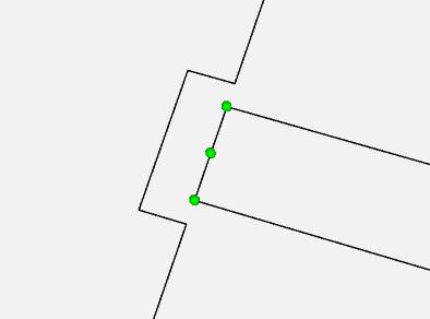
However, this shouldn’t affect the accuracy of the results, as the solver finds the shortest path possible between the terminals along the mesh cells to excite the model.
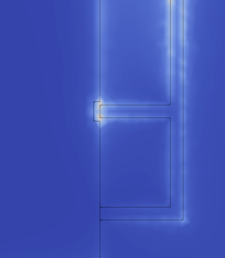
Mesh density around the port definition
On rare occasions, the mesh around the port definition might be too rough. If you notice a rough mesh (jagged Electric Field distribution) around where you defined the port, go back to the Mesh Generation screen, enable manual meshing and apply a finer refinement along the edges or face of the port.
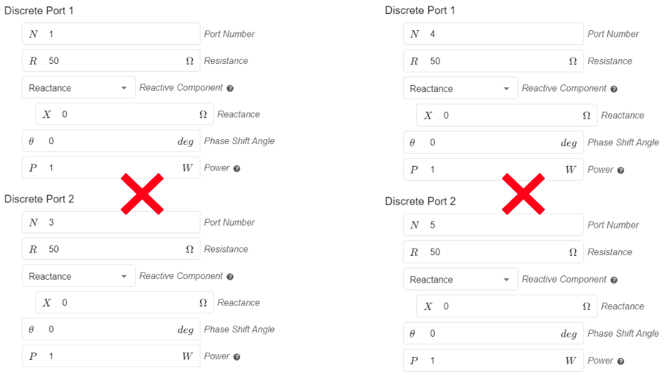
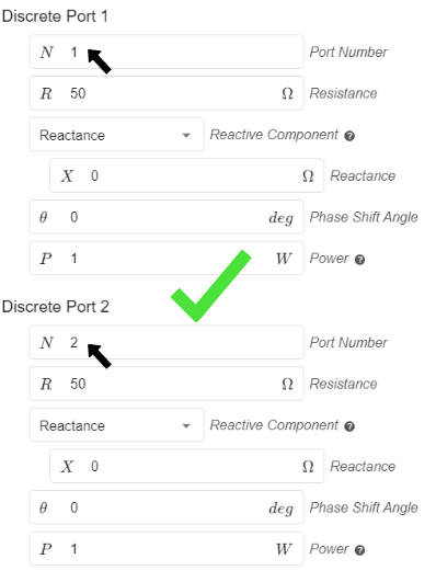
Multiple ports
When using multiple ports don’t forget to number each one with a different number sequentially, starting at number 1. If there are ports with the same port number this will cause problems!