Misalignment study
When we talk about static Wireless Charging simulations such as phone charging, we initially consider a perfect alignment between the phone and the charging pad – phone receiver coil is perfectly centered and on top of the transmitter coil, and the best conditions for charging are reached. In reality, when we put our phone on the charging pad, we might be in a hurry or accidentally move the phone, so that it is placed on the charging pad in a slightly deviated position.
When designing wireless charging systems, engineers need to evaluate different relative positioning between Transmitter and Receiver coils, to understand, for example, how the efficiency changes with different relative placement. To simplify the task, it is possible to perform misalignment study simulations, to check how the system behaves in different Receiver coil placement against the Transmitter coil.
In this article we will take a look how to set up and perform misalignment study in CENOS Wireless Charging software.

Concept
Misalignment study in CENOS is performed, using Motion functionality. If you have a full thermal analysis of your system, and you use Motion, you analyze one system behavior, where the parts are dynamically moving against each other. It is a transient process, because temperature in the system is influenced by the previous temperature distribution in the previous calculation time step.
Now, if you disable thermal analysis, but keep Motion, time steps are no longer connected to one another – for purely electromagnetic analysis it does not matter what was calculated in the previous time step, as that does not affect the next one. This way, if we use Motion to displace, for example, Rx coil, then each time step is a separate calculation of the same system, and we get a placement study, where within one time step we displace part of the system by some distance.
For example, if you define Rx movement in X direction with a velocity of 0.001 m/s, and calculate purely electromagnetic analysis for 5s, you get a placement study, where in each time step Rx is displaced in X direction by 1 mm, in total of 5 mm max displacement.
Setup
To correctly define misalignment study in CENOS WCH, some things need to be taken into account.
Negative inductance/impedance
First of all, for accurate misalignment study we need to enable Negative inductance/impedance calculation. In some cases larger displacements between Rx and Tx coils will result in drastic absolute value and direction changes of parameters such as mutual inductance or coupling coefficient, so we need to account for negative values to make sure we see the correct change in these parameters with increasingly large displacements.
You can enable Negative inductance/impedance in SIMULATION CONTROL under Advanced result settings.

Motion
Displacement is defined using velocity. You need to figure out how big of a displacement you want to see, and enter that as the velocity in the necessary direction (while keeping in mind that you set time step in SIMULATION CONTROL as 1 s – if time step will be different, then the displacement within one step will also be different).
Motion should be defined with constant velocity. To see how to do it in more detail, read our Defining motion article.
EM analysis
As mentioned before, for Placement study to work, you need to disable all Thermal analysis within your simulation. You can do that in every domain by changing enabled physics and disabling Thermal analysis.


Tips & tricks
Large array misalignment study
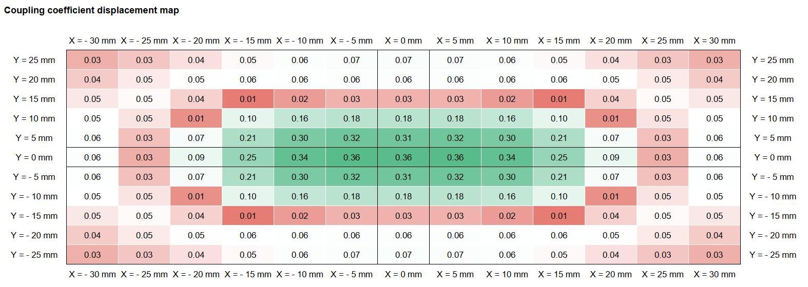
Setup described above is for a simple, linear displacement study, where we displace Rx coil in one direction. But what if we wanted to create a displacement map?
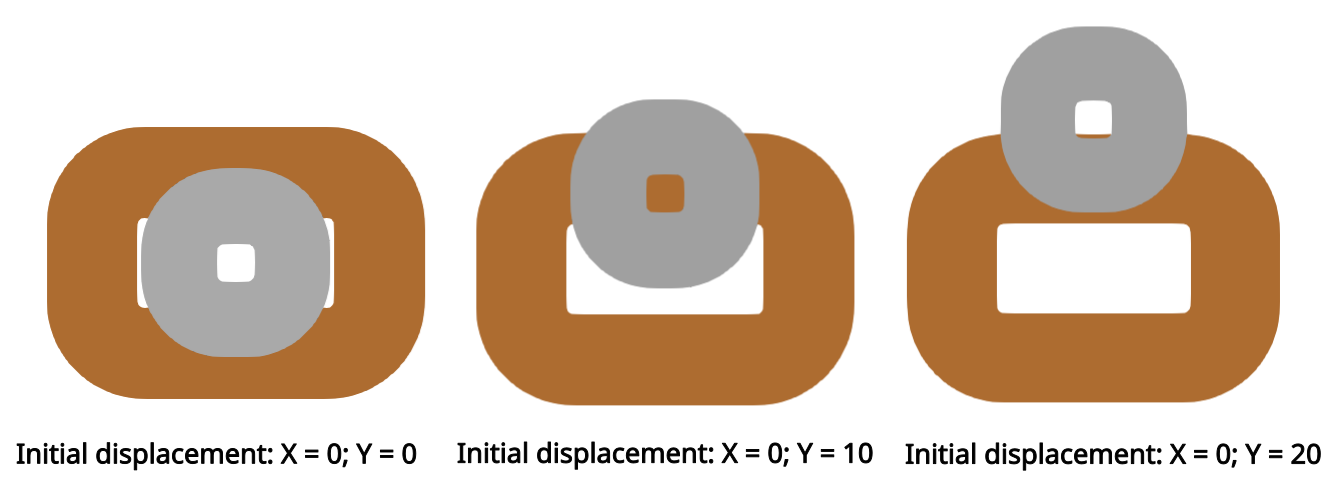
In such case we need to combine results of different runs, with different initial displacements. For example, I want to see how the process parameters change, if I displace my Rx coil by 30 mm in X direction, and 25 mm in Y direction, both with a step of 5 mm. I need to create an initial case, where the Rx coil is centered with the Tx coil, and run a placement study of 30 mm in X direction. I then need to displace the Rx coil by 5 mm in Y direction, and repeat.

Rx coil can be displaced directly in the CAD file, and it can be either reloaded in an existing simulation, or you can build a completely new one. When such runs are done, you can combine the results of each calculation, and create a displacement map.


