Manual meshing tips & tricks
When you reach the meshing stage in Cenos for the first time, you will encounter a window that looks like this:
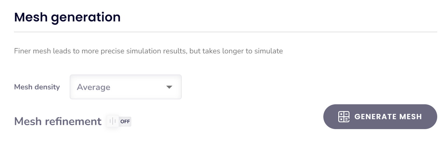
- You can either generate the mesh automatically, review it to determine if it meets your requirements, and then make manual adjustments as needed.
- Alternatively, you can enable Mesh Refinements beforehand to customize the mesh parameters prior to generation. However, we recommend starting with an automatically generated mesh and then refining it as needed.
Manual refinements overview
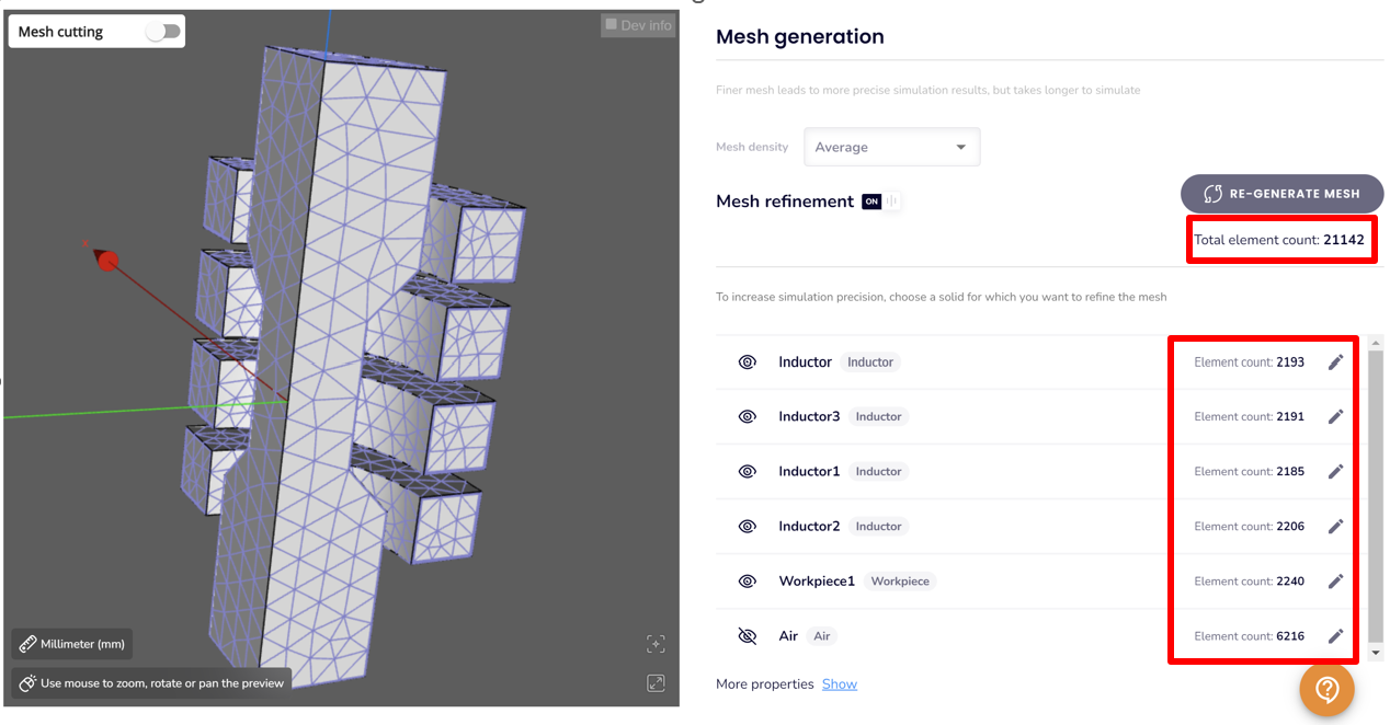
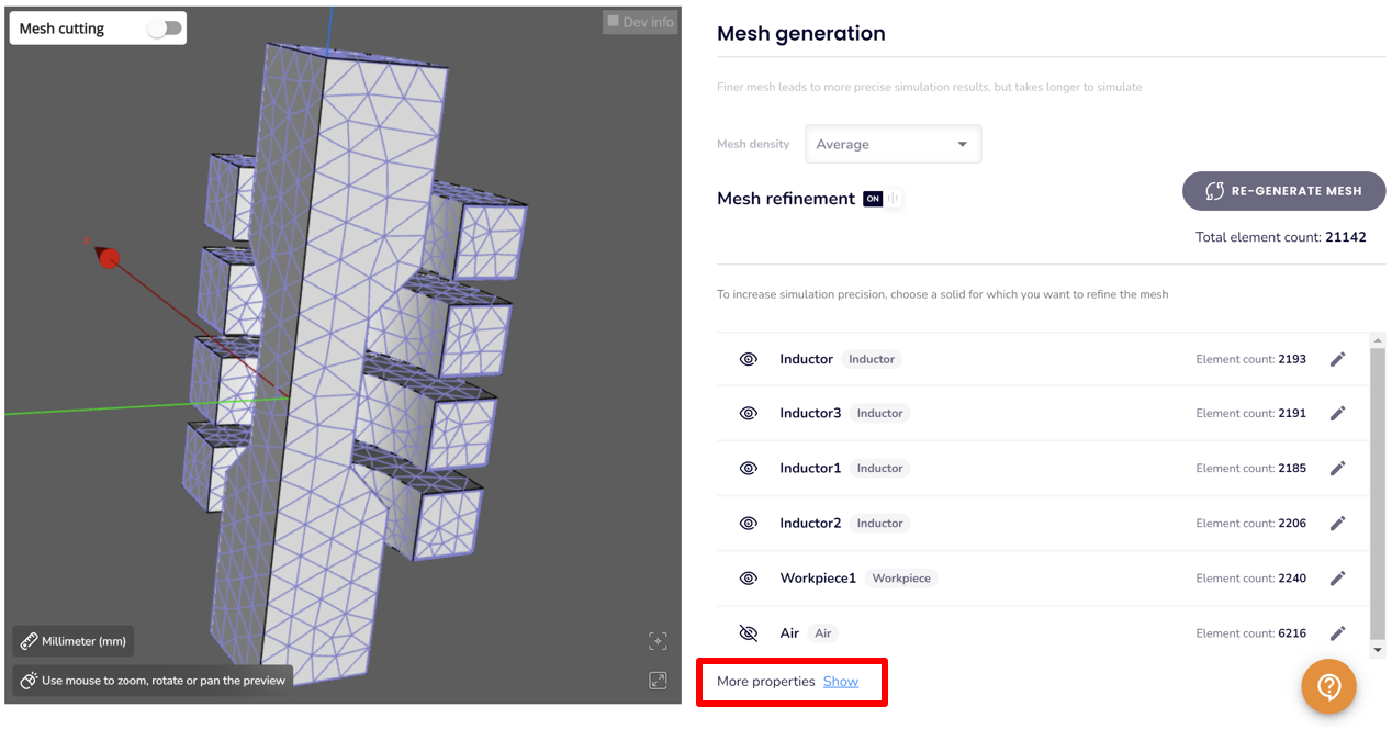
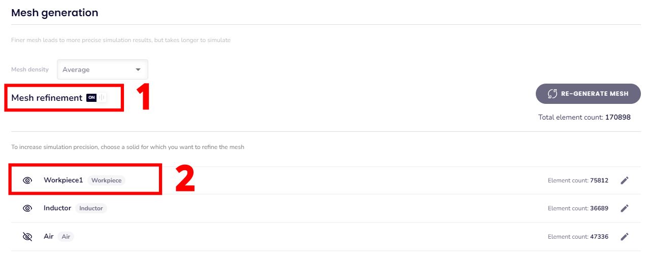
For the purpose of example on how to adjust the mesh manually we will start with automatic mesh generation. When it is done, you will see the total element count and element count in each domain.
Manual meshing for a specific domain
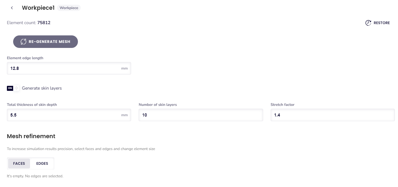
To refine the mesh for a specific domain, click on the domain to open a dedicated window for mesh adjustments. For instance, selecting the workpiece will open the Workpiece meshing window, where you can tailor the mesh settings for that region.
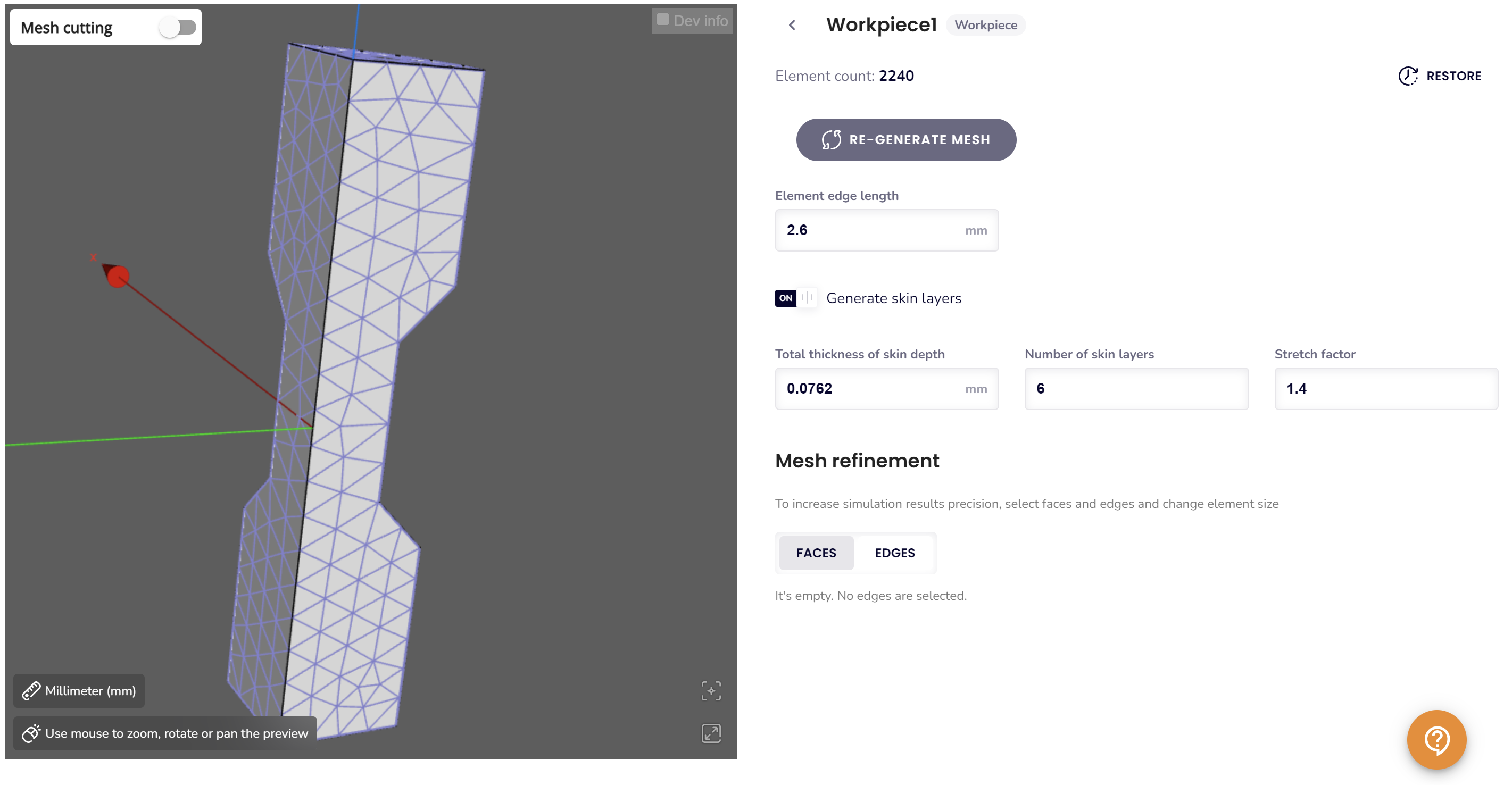
When refining the mesh of a specific domain, you have access to several tools and customization options to optimize the mesh for your requirements.
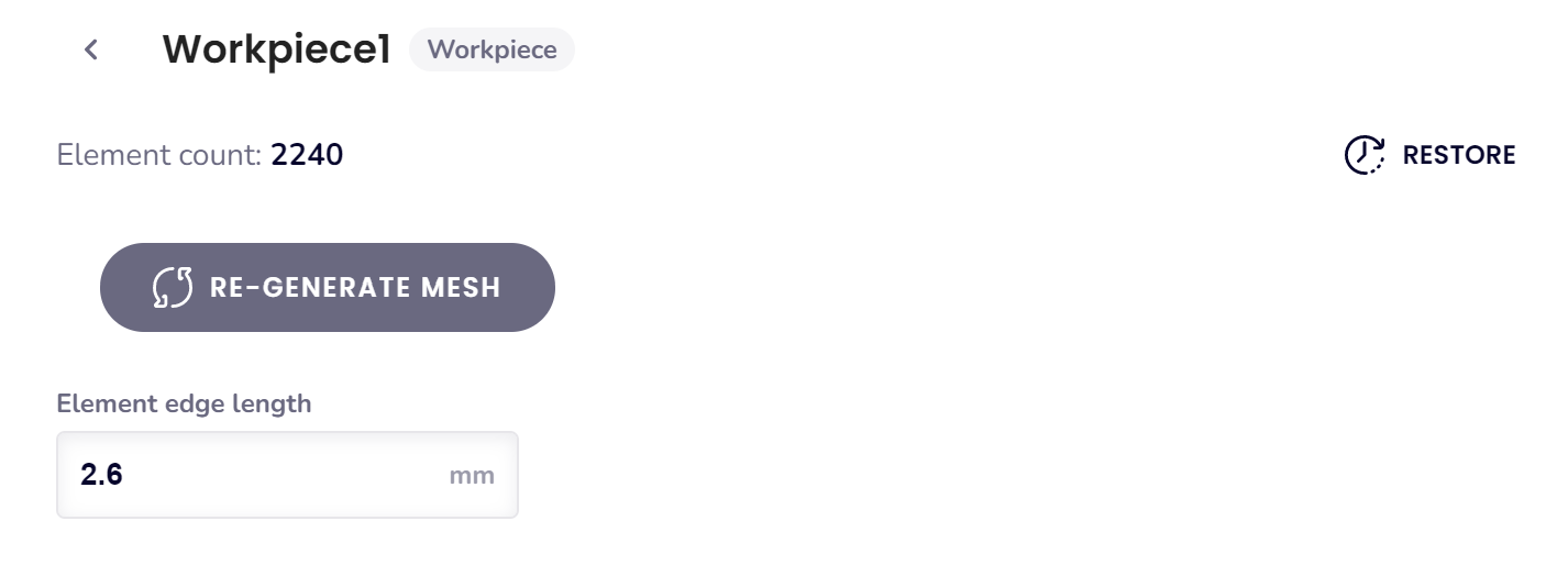
Element edge length adjustment:
Allows you to set a constraint on the element edge lengths within the selected domain.
- This ensures uniformity or precision in specific regions by defining a maximum or desired edge length for the elements
Skin-layer adjustments:
- Total thickness of skin depth: Modify the thickness of the layer near surfaces to better capture gradients.
- Number of skin layers: Control the number of layers within the skin region.
- Stretch factor: Adjust the growth rate of elements within the skin-layer.
- Generate skin-layers (option to disable): While possible, turning off skin-layers may lead to incorrect or less accurate results.

Face or Edge Refinements:
Fine-tune the mesh on specific faces or edges within the domain for increased resolution.
- Useful for areas of high gradient or regions requiring greater precision.
Global mesh parameters
You can also modify global mesh parameters, which will apply to all domains. These settings are located under the “More properties here” section at the bottom of the meshing window.
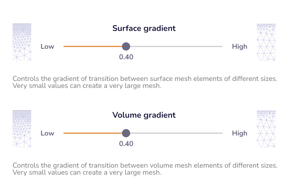
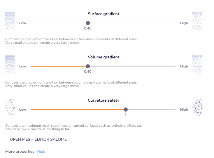
Volume and Surface gradients
Volume and surface gradients control the rate of transition from smaller to larger elements in the mesh.
- Lower Gradient Values: Result in a more uniform mesh with less variation in element size but generally lead to a denser mesh. This is useful for improving accuracy in regions where high precision is required.
- Higher Gradient Values: Allow for a coarser mesh with fewer elements by permitting greater variation in element size. This can optimize computational resources and reduce simulation time.
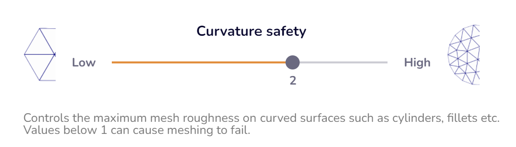
Curvature safety
For geometries with curved features (e.g., round-profile inductors, workpieces), adjusting the curvature safety parameter can be helpful:
- Increase Curvature Safety: Improves mesh resolution for domains with rounded shapes, ensuring better accuracy in capturing curvature details. This is useful if the current mesh appears insufficiently refined in curved areas.
- Decrease Curvature Safety: Reduces mesh density in curved regions, optimizing element count and computational efficiency if the mesh is unnecessarily dense.
This adjustment ensures the mesh is appropriately refined to balance accuracy and resource use in curved geometries.
Tips and tricks
In some cases, an automatically generated mesh may be excessively dense, making it impractical due to high computational resource demands. Here are steps you can take to reduce the mesh element count effectively:
- Adjust the Volume Gradient:
- Start by increasing the volume gradient from the default value of 0.4 to 0.8.
- This reduces overall mesh density while maintaining reasonable accuracy.
- Refine the Curvature Safety:
- Lower the curvature safety from 2.0 to 1.5, or try even smaller values like 1.1.
- This reduces the mesh resolution around curved geometries and helps minimize the element count further.
- Regenerate the Mesh:
- After making these adjustments, regenerate the mesh to evaluate the impact of the changes.
- Review Domains with Skin Layers:
- Domains with skin layers often contribute significantly to the total element count.
- If your simulation uses materials with an enabled B-H curve, Cenos typically generates 10 skin layers by default. However, this can often be reduced.
- Recalculate the Minimal Skin Layer Depth:
Use an online skin depth calculator to determine the required depth for resolving the layer. Input the material’s highest conductivity (typically at 20°C) and the highest frequency in your simulation.- Adjust the skin depth to this calculated value.
- Reduce the number of skin layers to 4-7 instead of the default 10.
- Iterate: You may need to regenerate the mesh multiple times to find the optimal balance of skin layer parameters.
- Increase the Element Edge Length in Select Domains:
- For domains where high precision is less critical (e.g., inductors), increase the element edge length.
- Inductor domains typically only require fine resolution at the surface, where the highest current densities occur. Larger elements can be used in the volumetric regions to reduce the mesh size further.
What to do if mesh fails
From time to time you might encounter some mesh failures. Here you can find the most common errors and what to do if you encounter them.
Meshing fails with “Could not generate skin layers”
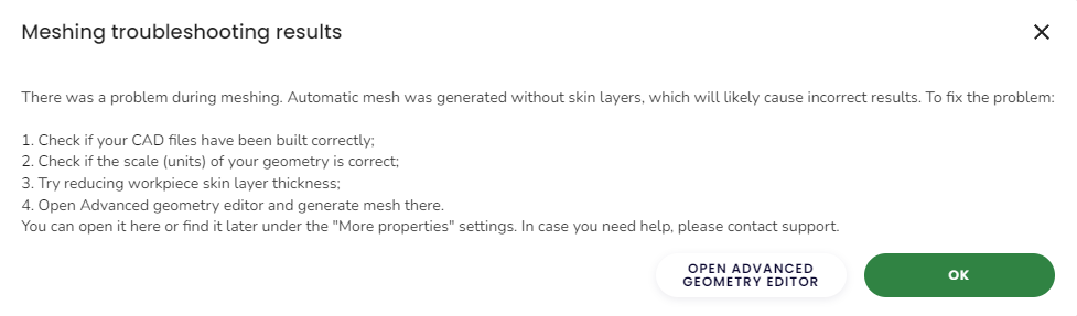
In this case the volumetric mesh is still generated, however, the skin layers are not generated.
It is not suggested to move onto running the case, since the results might be quite inaccurate as the skin layers are necessary for precise calculations.
In this case you can check if the mesh has any places where the mesh suddenly becomes a lot finer, since those places might cause issues generating skin layers – there may be some gaps, small elements or some other CAD related issue that can be easily solved by modifying the geometry in your CAD software and uploading it to CENOS again.

Review your geometry – are all details necessary? Removing small details will allow for better mesh generation, as well as speed up the calculation.
Meshing fails completely
A popup window will appear where the geometry will be highlighted in some places. Please note those places and review them in your CAD software. If there you see any gaps, overlaps, etc., those are most likely the issue. Note that the highlighted places might be small and not easily noticeable.
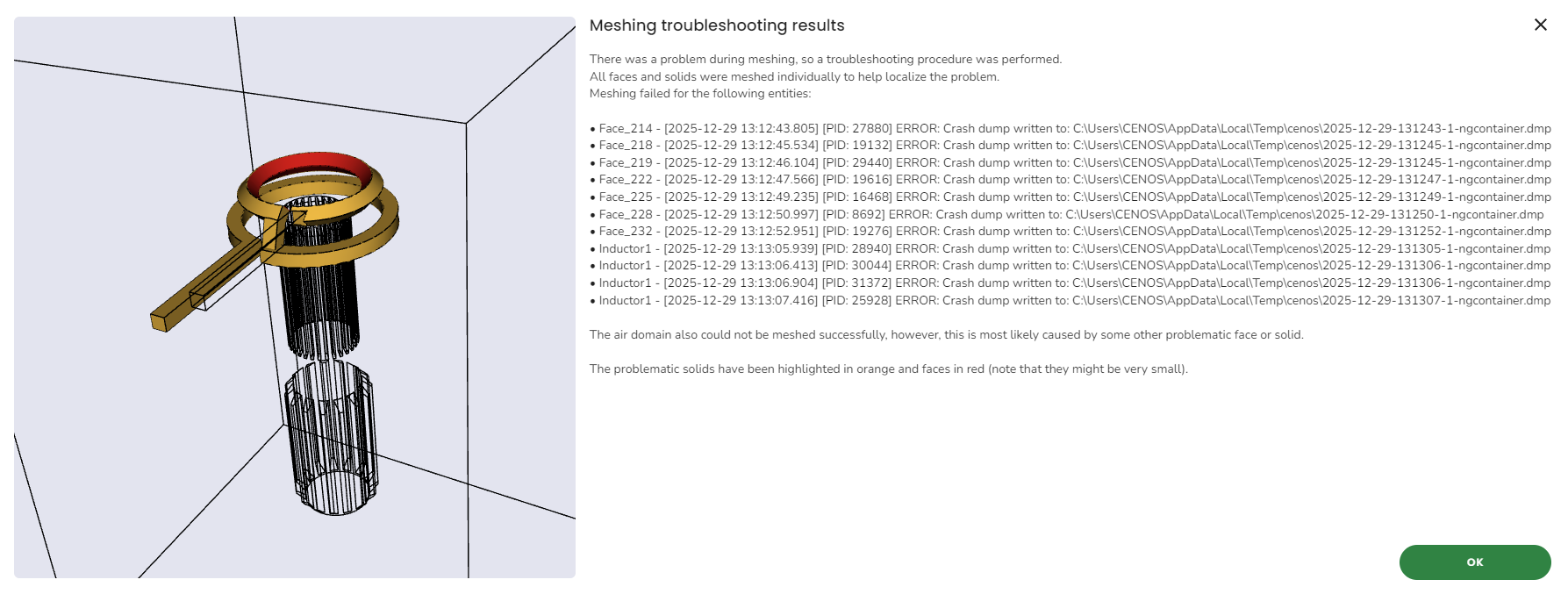
This mesh failure is most likely caused by the geometry itself. You can refer to this article about how to create a good CAD.
If you have many small details, curves, fillets, chamfers etc., please review the geometry and remove as many of them as you can. If there are details that cannot be removed, make sure to simplify them as much as possible.
Next also check that each solid has been fused as a single solid.
Make sure that there are no geometry overlaps or tiny gaps – those can cause the mesh generation to cause errors as well.
ERROR: Error while creating a mesh: Mesh has too thin prism layers. Please check your meshing input! If problem persists, contact support!
This one is most likely connected to the size of the geometry and the size of the mesh you want to create – if, for example, you have a large geometry and a big element edge length, but small skin layers – this might cause thin elements and this error. Another case can happen if you want to create small elements but large skin layers.
In this case you should review your geometry – make sure that it is the correct size.
Also review the mesh – make sure that the values make sense – for example, element edge length 20mm and skin layers 2mm make sense, on the other hand, 200mm edge length and 2mm skin layers do not make sense, unless your geometry is not big with no small details. The same goes the other way around.
How to refine small details
If you have small geometrical details that cannot be removed, you can use mesh refinements to resolve them better. You can go into the object’s tab in the meshing section and input a lower number as the element edge length for the whole solid or you can choose the closest small edges around the details and input a smaller number there.
The element edge length in this case should be chosen like this: measure the smallest detail you have in the geometry and input a value approximately as that.
For example, if you have detailed elements that have the element edge length of 2 mm, you can input 1 to 4 mm as the element edge length. If you input that value for the whole solid, the mesh will be quite fine and will have many elements, making the calculation time longer. So input this for the whole solid only if the whole solid is with small details.
If only a few small parts have such details, select the detailed and some surrounding faces and input the smaller value only for those. This will make sure that the detailed faces have a finer mesh, allowing for skin layer generation, but the rest of the solid will have rougher mesh.
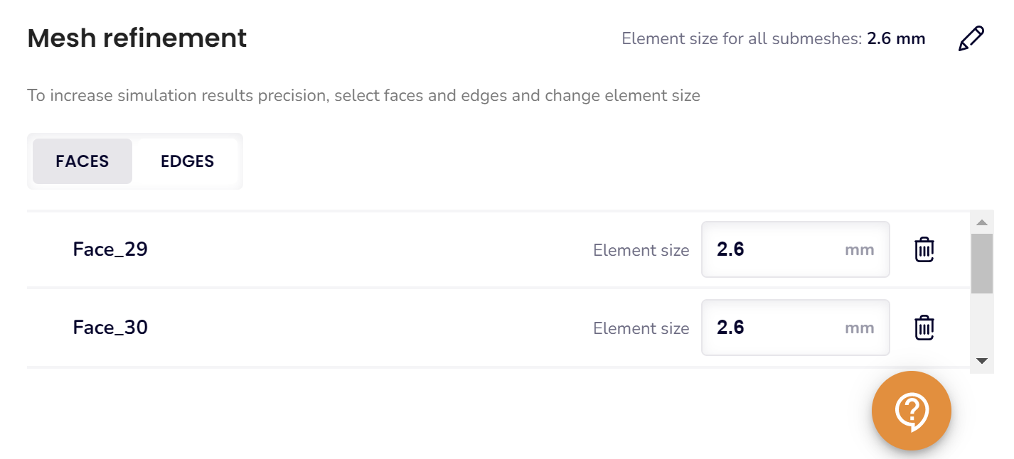
For example, here you can see that the whole workpiece has the element edge length 25.5 mm, however, one face has been selected and element size has been defined as 5 mm.
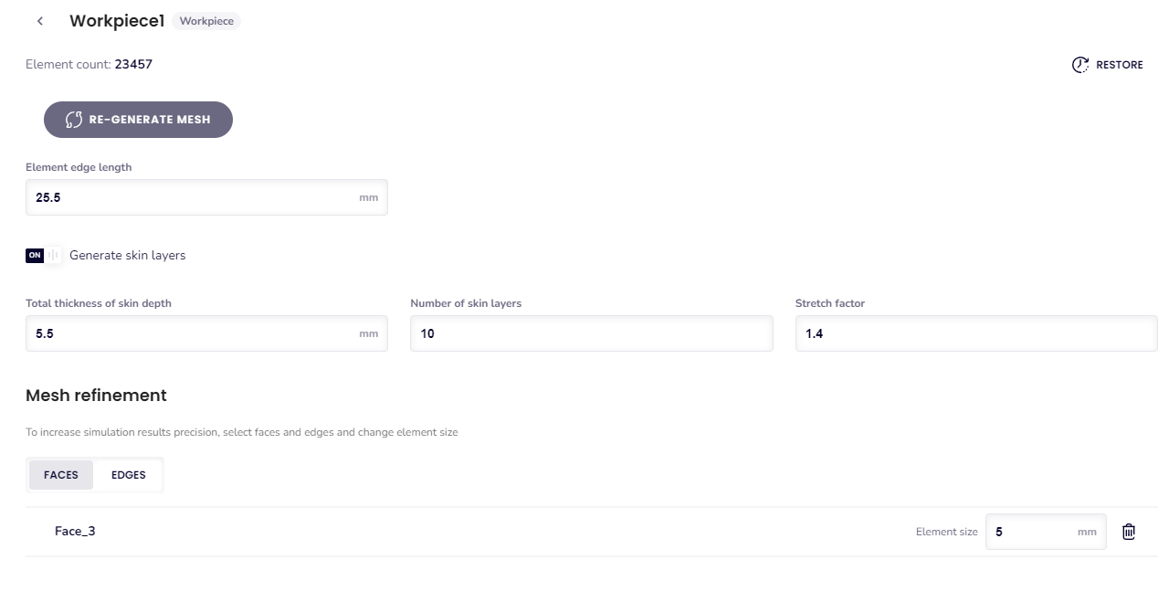
This results in that one face having finer mesh than the rest of the workpiece.
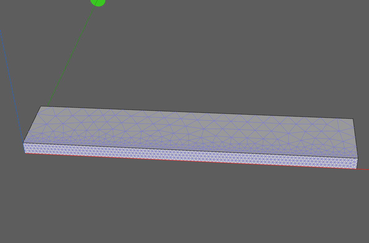
You can also choose edges this way. This allows you to make the mesh finer in the places where there are small details that cannot be removed, but the rest of the mesh stays rougher, so the mesh size does not grow a lot and calculation time also stays reasonable.
How to optimize mesh size
If there are a lot of mesh elements, you can also use the general mesh refinement options.
Firstly, if the air or some other solid has many elements, they can be made bigger by using the volume gradient refinement.
If your geometry has a lot of curves, you can use the curvature safety refinement.
Next, also check what element edge length has been input for the solid with curves. If the value is too big, the mesh will not generate or throw additional errors.
To make sure that the mesh can generate if you have lowered the curvature safety, measure the curved solid’s thinnest part and set the element edge length for that solid as that value.
If, for example, you have a curved inductor that has the diameter of 3 mm, make sure that the element edge length is not bigger than 3 mm when lowering the curvature safety.
The more you lower the curvature safety, the more you need to think about the element edge length values for the curved solid.
For example, if you lower the curvature safety from 2 to 1.8, the default values might still work alright.
However, the closer you get to 1, the more you need to lower the element edge length for the curved solid. In this case, with a curved inductor with diameter of 3 mm, if you set the curvature safety to 1, you might even have to set element edge length for the inductor as low as 1 mm.
If you have tried to simplify the geometry, refine the mesh and still experience meshing issues, please send the case over to our support team.
