FreeCAD basics for RF geometry
Geometry creation in FreeCAD
For geometry manipulations CENOS Radio Frequency uses a very strong geometry editor – FreeCAD. This editor is used in the Geometry Editor workflow, so it is important for us to understand how to work with FreeCAD.
Watch a short video on how to use FreeCAD for CENOS Radio Frequency app:
Geometry import
Sometimes when building an RF simulation, you will already have pre-made geometry, which you can import into FreeCAD for additional geometry manipulations.
STEP/IGES
You can easily import your CAD file in IGES or STEP file formats.
To import such files, open Geometry Editor and simply drag & drop your geometry into FreeCAD!
KiCAD PCB files
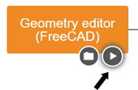
To import KiCAD PCB files directly into CENOS : RF, select the Geometry Editor approach and there you will need to click on the folder icon to load your geometry.
Once you have selected your file you will return to the main CENOS interface where you will now click on the play icon. Then the software will ask you to save the case and, after this, FreeCAD will automatically open with your geometry!
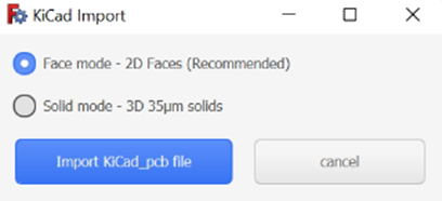
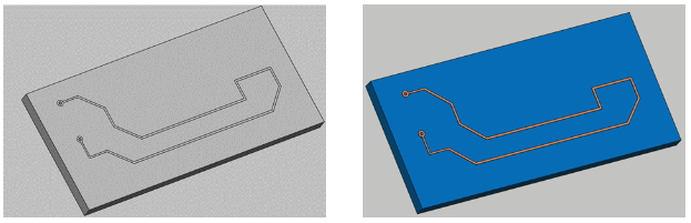
You have the option to use your model completely in 3D or flatten the thin conductive parts, such as tracks, to have them in 2D. We recommend selecting the Faces mode, as the results will not be significantly affected but the mesh will be easier to create and the calculation time will be reduced!
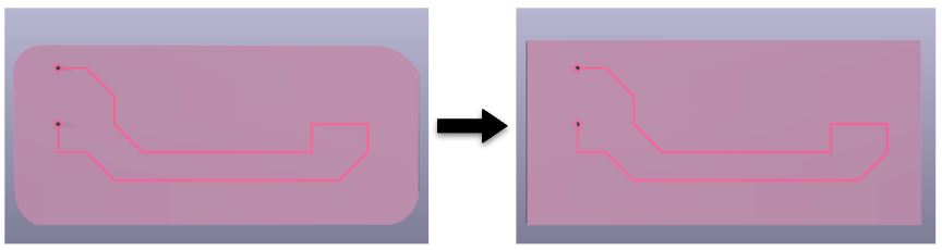
Note: We recommend that for the substrate you use a geometric figure without curvatures since this would cause troubles reading the geometry and it will not be imported correctly into FreecCAD. If the curvatures in the substrate are important in your model, you can create it within FreeCAD once the model has already been imported.
Unit scaling
CAD files which are imported in FreeCAD must be in the correct units – milimeters. If your geometry is scaled incorrectly, you need to rescale it, otherwise meshing problems will occur.
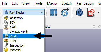
To scale your geometry:
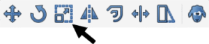
- Switch to Draft workbench.
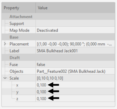
- In Tree View select your geometry and click Clone (this function will create a scalable copy of your geometry).

- Once the clone object is created, scale your geometry in Properties. Make sure that the scale factor is the same in every direction to avoid distorting your geometry!
Note: As an alternative to geometry scaling you can use Scale function, but it will not work on every geometry, as opposed to the Clone approach.
CAD compound check
If you have imported one or more CAD files and stumble into a problem either at meshing or anywhere else, it might be an indicator that the CAD file is actually not a solid, but a compound of surfaces, which can cause problems for FreeCAD.
To check if your CAD is a solid:
- Navigate to the Part workbench.
- Click on the object in Tree View and open the Python console (right-click on the icon and select “Send to Python console”).
- At the bottom, the Python console will open. Type len(obj.Shape.Solids) and press Enter.
- Take a look at the output.
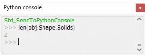
The number of solids indicate how many volumes are there. If this number is high, evaluate the quality of your CAD file!
Note: If you get an error message and cannot display the number of solids, click Edit → Send to python console, and redo the previous steps!
Create a Body
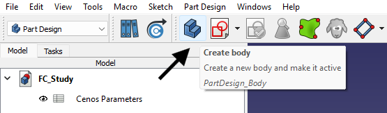
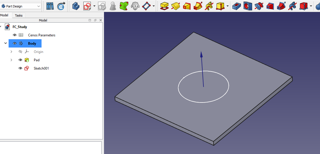
Once the FreeCAD window opens, you will be placed in the Part Design workbench. This workbench in FreeCAD is a powerful environment for creating solid models. Below is an explanation of its key tools that you might find useful.
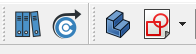
Before doing anything else, you’ll want to create a Body. Think of it as the container for everything you’re about to build — sketches, extrusions, cuts, and more. Just click the “Create new body” icon, and you’re ready to go.
Sketches
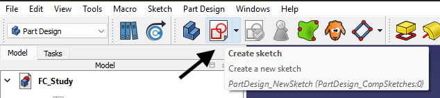
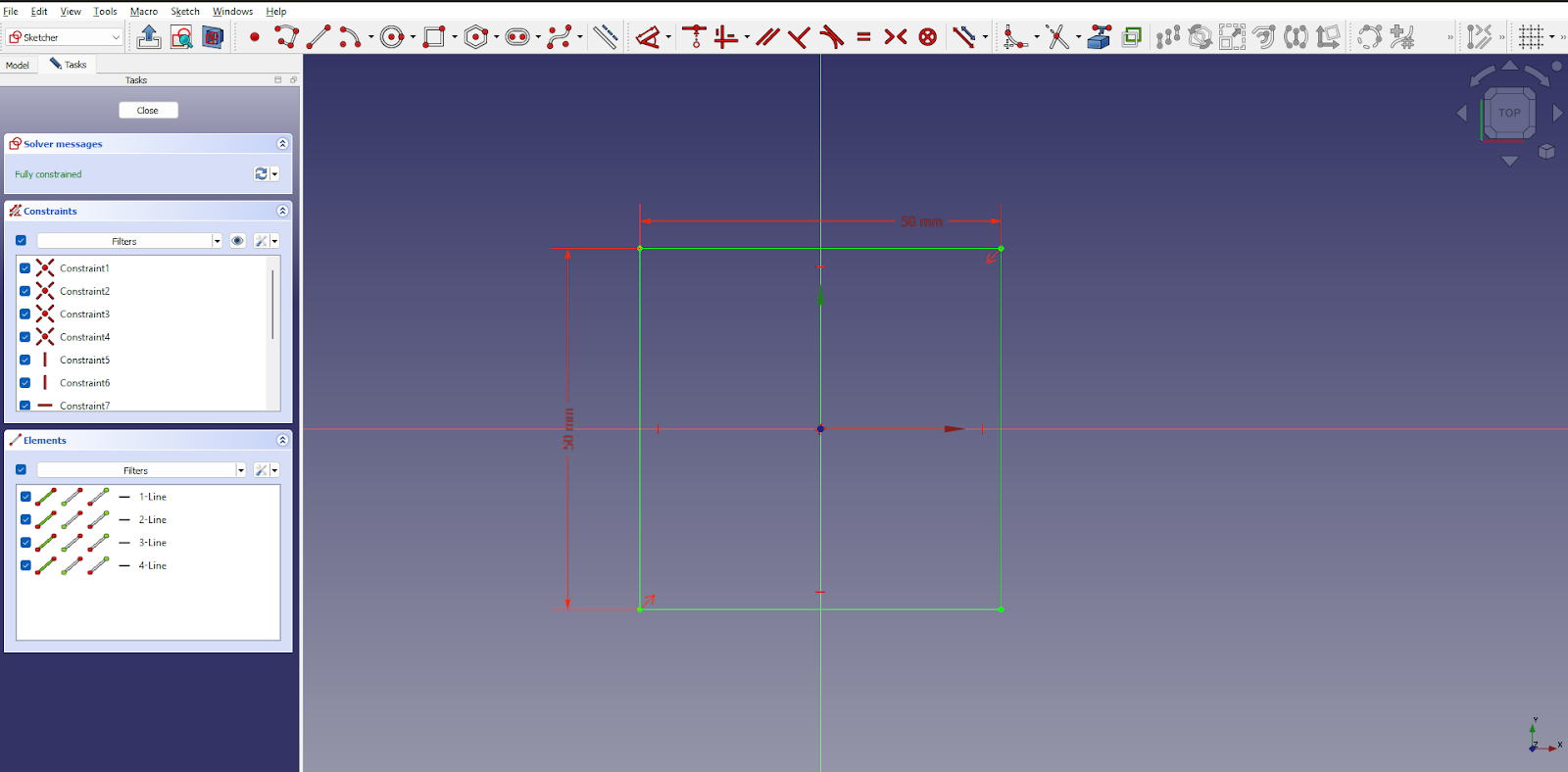
Click “Create new sketch”. Select a base plane or a flat face of a body. You’ll be taken into the Sketcher environment, where you can draw basic shapes like rectangles, circles, or custom profiles. Here, it’s important to use constraints to lock down your design. These define things like dimensions, symmetry, or alignment. A fully constrained sketch gives you a stable foundation for 3D operations.
From scratch
Click the “Create Sketch” button. FreeCAD will prompt you to pick a working plane: XY, XZ, or YZ. Choose the one that fits your design best. For example, XY is common for flat base shapes.
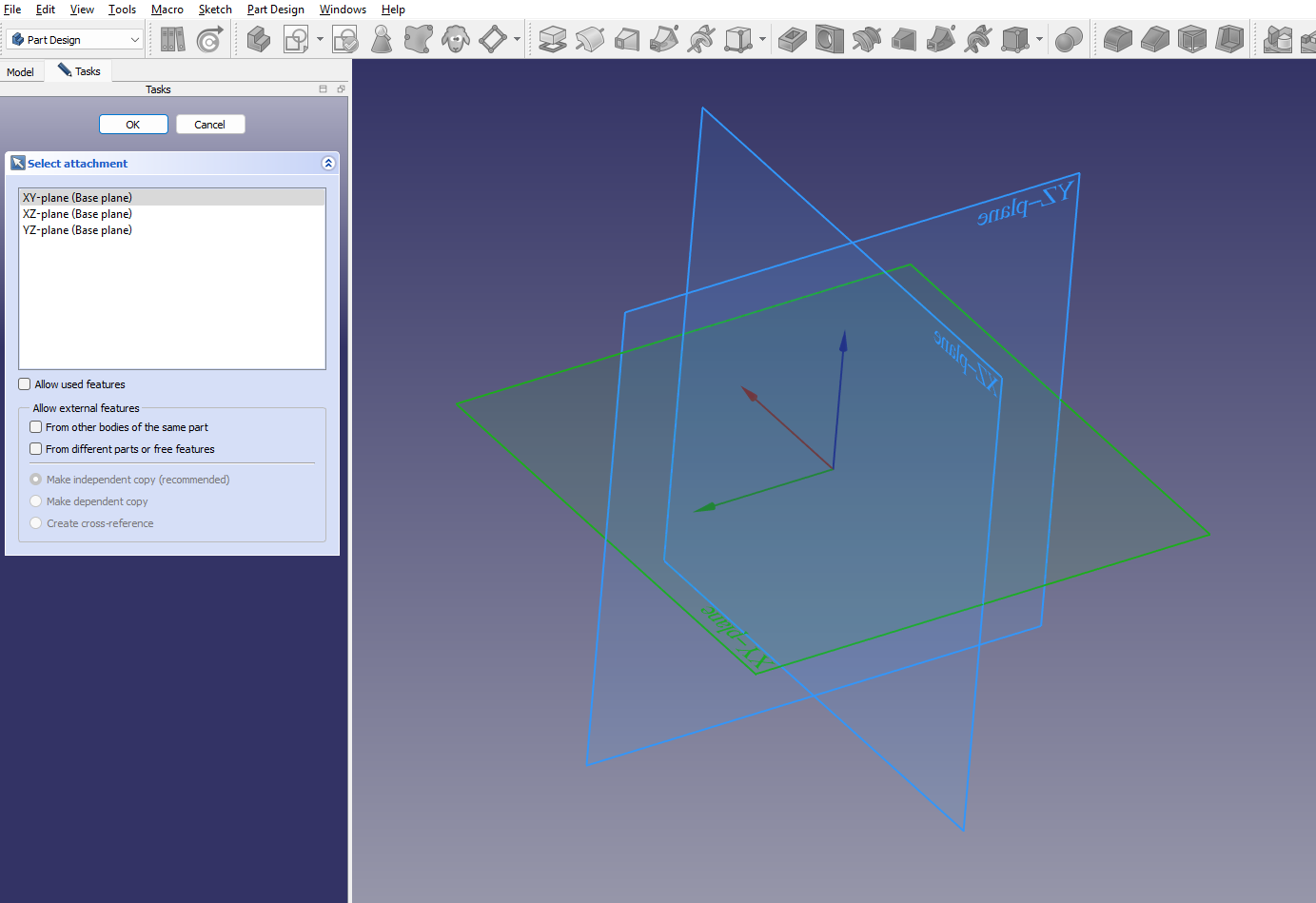
You’ll enter the Sketcher Workbench, where you can use different tools. Once you’re done, click “Close” in the toolbar to return to Part Design.
On Volumes
If you already have a solid body — like a block, cylinder, or any other shape — and want to add features like holes, extrusions, or cuts, you can click on any flat face of your existing solid.
This tells FreeCAD where to attach the new sketch. FreeCAD will automatically attach the sketch to the selected face, aligning it perfectly.
When you close the sketch, you will notice that the sketch will be on the surface you selected!
3D volumes
For a lot of times it will be necessary to create 3D geometries, not only 2D sketches. Fortunately 3D modeling in FreeCAD is very straightforward!
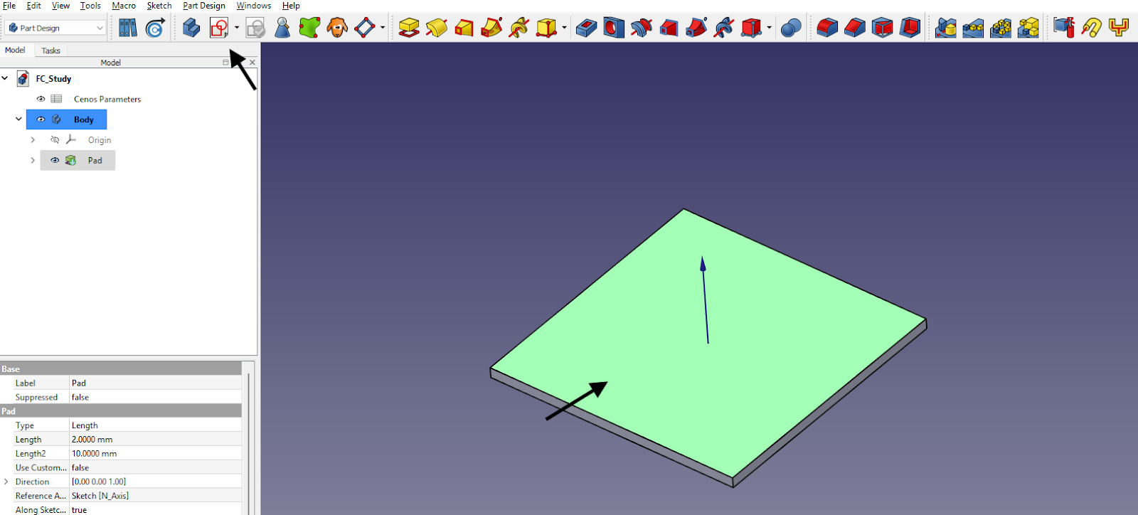
Turning a Sketch into a 3D Shape: Pad Tool
Once your sketch is ready, you can transform it into a solid using the Pad tool. You can choose how far it extends and in which direction.
You need to first create a sketch you need.
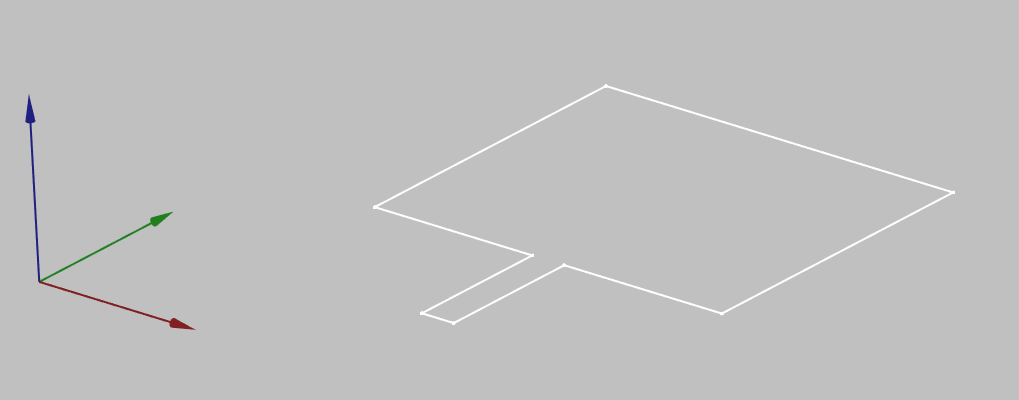
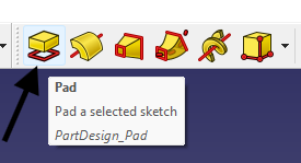
Then switch to Part Design workbench, select the sketch desired and click Pad a selected sketch.
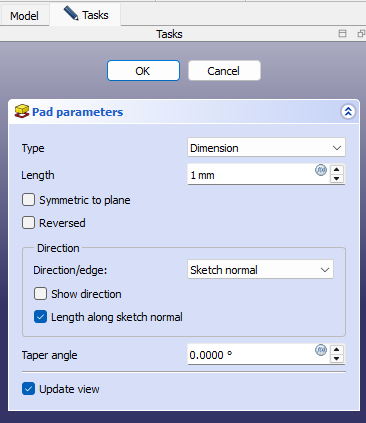
In the Pad properties window define the pad length. Once done, click OK.
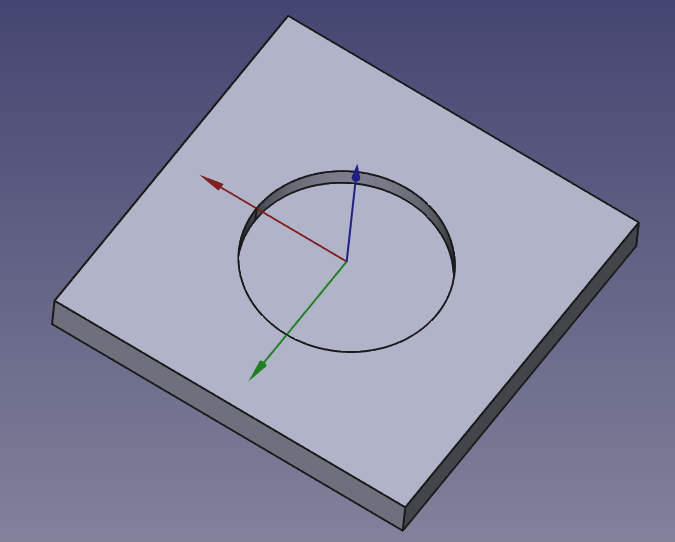
Pocket tool
The Pocket tool is used to remove material from an existing solid body by cutting it along a 2D sketch. This operation is perfect for creating holes, grooves, slots, and other cutouts in your design.
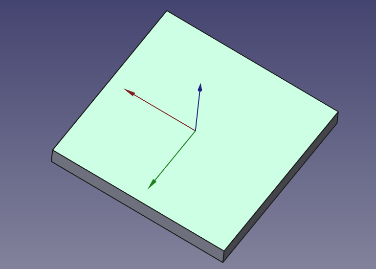
Start with a solid body. You need an existing 3D solid to use the Pocket tool. Typically, this is created using the Pad tool.
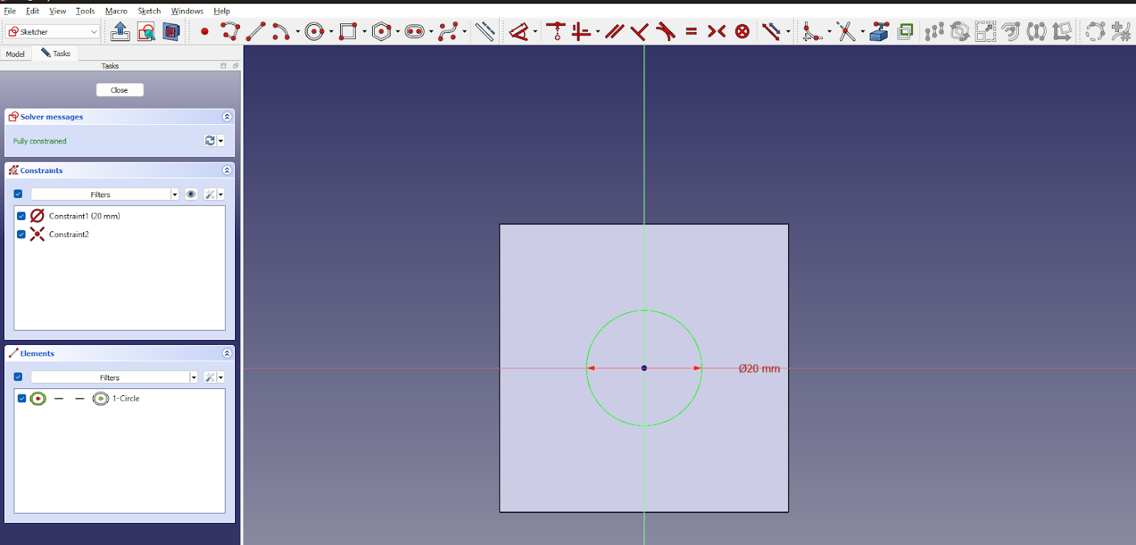
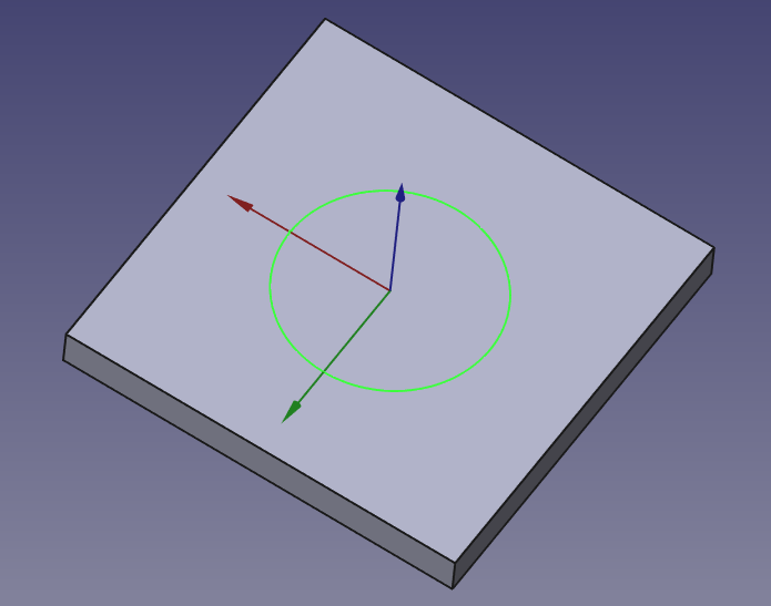
Then create a sketch on a face:
- Select a flat face of your solid.
- Click “Create Sketch” and draw the 2D shape you want to remove (e.g., a circle for a hole, a rectangle for a slot).
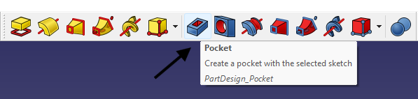
Apply the Pocket:
- With the sketch selected, click the Pocket icon in the Part Design toolbar.
This opens the Pocket parameters dialog where you can choose from several extrusion modes and set the depth.
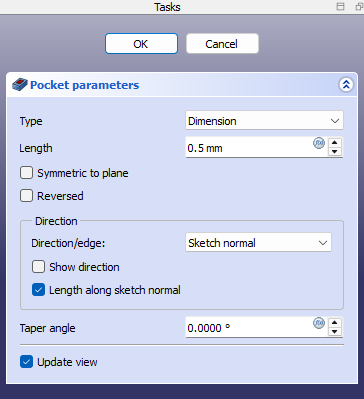
Click OK to finalize the cut.
Basic Shapes
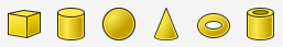
For the simplest volume objects like cubes, spheres or cylinders, FreeCAD offers an easy way of creating such geometries. As you open FreeCAD, you will be automatically put in Part workbench. There you can simply select any geometry you want and build it.
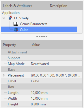
As you select an object, it will be built with a pre-defined size. To change the size of your geometry, select your object and change its properties.
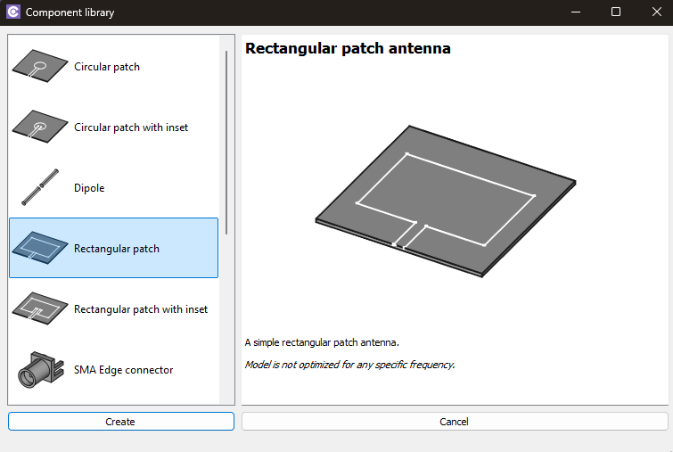
Component library
You can use CENOS Component Library templates to build or add antenna or SMA connector geometries.
Antenna models
Select the model you want to build and click Create.
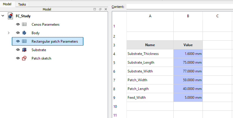
You can change the template parameters by clicking on the spreadsheet titled with the name of the model you selected from the component library.
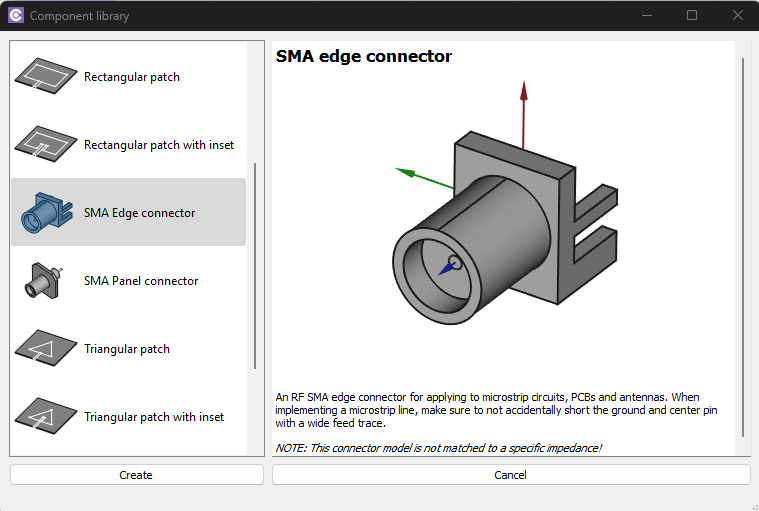
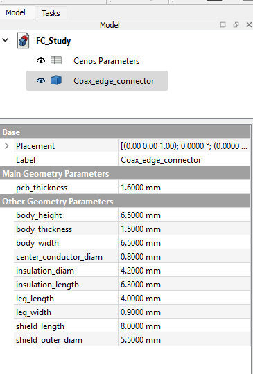
Coaxial edge connector
Select Coaxial edge connector and click Create.
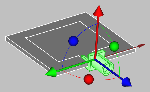
The connector will be automatically placed in your workbench, so you can position it by right-clicking on it in the tree view and selecting Transform.
To change the size of the connector, select it in the tree view and edit the Property tab to suit your application.
Wire thickness
To create a wire antenna from scratch, you need to create a sketch of your antenna, and then define the thickness of your wire:
- CREATE A SKETCH
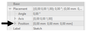
- For 2D sketches you can set sketch position in its properties (In sketch properties Base → Placement → Position)
- To build 3D sketches, use Draft Workbench → Drafting → Line. There you will need to build lines one by one and adjust the Start and End points to match your design.
- For helixes or spirals use Create Primitives function in Part workbench.
- For 2D sketches you can set sketch position in its properties (In sketch properties Base → Placement → Position)
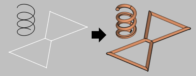
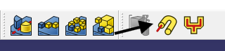
- Create a wire with volume from the edges, select your shape, click Wire thickness tool in Part Workbench and define the wire thickness.
Note: Sometimes when building wires, the visualization will appear like this:
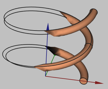
This is a visualization problem, which does not affect the geometry itself. You can continue and use this geometry in your setup!
Useful Tips, Tricks and Shortcuts for working with FreeCAD
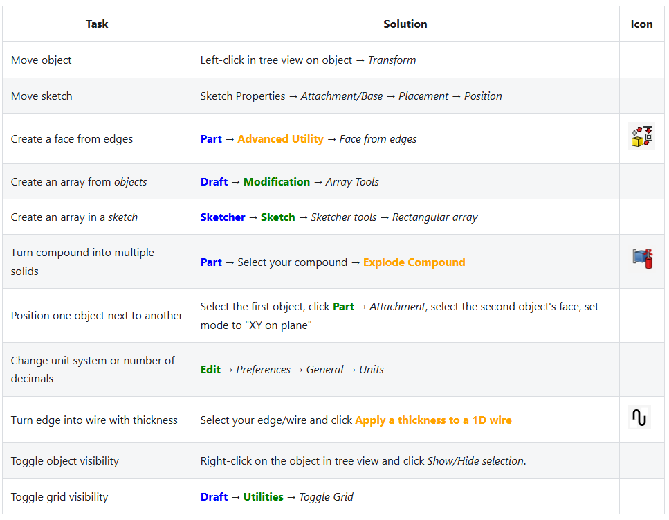
Common tasks
Useful shortcuts
| Function | Shortcut |
|---|---|
| Toggle object visibility | Space |
| Set camera rotation center | Middle-click |
| Pan camera | Left-click |
| Rectangle select objects | Shift+B |
| Rectangle select elements | Shift+E |
| Import File | Drag&Drop |
