Defining coils
Wireless charging systems can consist of many different elements. Insulations, ferrites, shielding, metallic components and many other objects can be present, but at the heart of every wireless charging system are wireless charging coils.
Receiver and Transmitter coils and their operational parameters are vital to every wireless charging system behavior, and because of this their physical definition is also vital for every simulation of such systems.
In this article we will take a look at how to correctly define Receiver and Transmitter coils in CENOS Wireless Charging software.
Overview
Besides current frequency, which for both Tx and Rx coils is defined within SIMULATION CONTROL tab, every other definition can be found in respective COIL TRANSMITTER and COIL RECEIVER tabs.
Transmitter (or Tx) coils are the power source of wireless charging system. There can be one or multiple transmitter coils, and every coil within one system can be defined differently.
Same goes for Receiver (or Rx) coils. You can simulate different Rx coils within one simulation with different physical and geometrical properties.
Unless you enable LTSpice coupling, in which case applied current/voltage and load will be taken from LTSpice file, you need to define these values in the respective coil tabs, together with coil geometrical characteristics.
Geometrical parameters
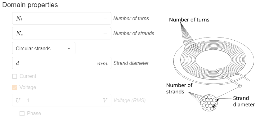
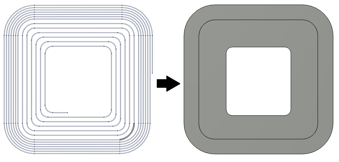
Since CENOS uses simplified calculation method for stranded wire coil calculations, we don’t need to resolve each strand in our CAD model – instead, we can import coils as solid blocks. However, physical characteristics still need to be defined, so that CENOS can model coil behavior correctly.
Physical parameter definition is the same for both Tx and Rx coils!
To account for geometrical properties of coils, 3 parameters need to be defined:
-
Number of turns – in how many turns stranded wire is twisted to get the final coil;
-
Number of strands – how many strands are inside the stranded wire;
-
Circular strands / Rectangular strands – in most wireless charging applications circular strands are used, and they are set by default. In case of a coil that is printed on a PCB board, this should be changed to Rectangular coils;
-
Strand size – diameter or height/width for circular or rectangular strands.

Physical parameters
Depending on what kind of coil you define – Tx or Rx, you will have to define either excitation (applied current) or load.
Excitation
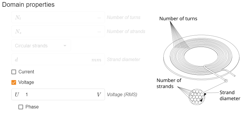
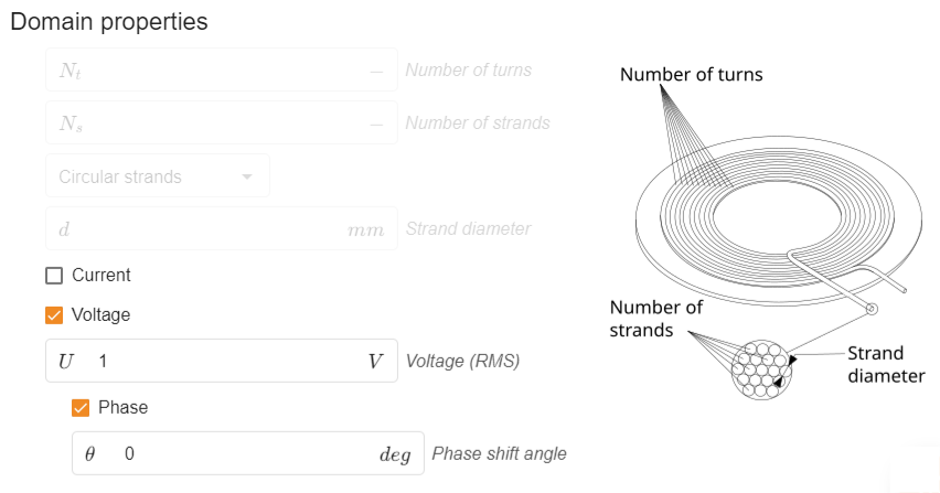
For Tx coil either Current or Voltage RMS values can be applied. If multiple coils are present, Phase shift between different coils can be defined.

Load
On Rx coils we usually apply some kind of a load, so that we can accurately predict what current and voltage values are actually present on the Rx coil. We can define Load in 3 ways:
-
Open Circuit – Calculates system as an open circuit on the receiving end. This approach will not provide current or power on Rx coil, but will provide maximum possible voltage value on the Rx coil.
-
Short Circuit – Calculates system as a short circuit on the receiving end. This approach will not provide voltage or power on Rx coil, but will provide maximum possible current value on the Rx coil.
-
Load – Calculates system with a custom load on the Rx coil. Will provide accurate current, voltage and power values on the Rx coil.

Tips & Tricks
Even though the coil definition is relatively simple, it is possible to tweak it in many different ways to define the system as it is in the physical world.
How to energize Rx coils
In some applications, such as EV charging, Rx coil is not passive, but instead it also has current applied to it. To model that, in COIL RECEIVER tab you need to change Domain type from Stranded Coil Rx to Stranded Coil Tx. This will allow you to energize both coils, and in the results you will see the interaction between Tx and Rx coil, even if the Rx coil is also energized!


Layered coils
If your coils are wound not in one, but multiple layers, you can account for such layers by simply adjusting the number of windings. If you have 10 windings in one layer, and have 3 layers in total, you can create your CAD file for that coil as a solid that encompasses all 3 layers, and in physics simply define 10 x 3 = 30 layers.

Since current density to the coil is calculated as homogeneous, and if your coil windings are uniformly distributed, there won’t be any inaccuracies during calculation!
Double-d coils
To simulate double-d coils in CENOS, you will need to split the coil into 2 sections, and import as 2 separate coils. In Geometry Roles, define each as a separate coil.

In Physics, you will need to enable Negative inductance/impedance under Advanced result settings, which will orient both halves of the double-d coil in the same direction.

Under each coil tabs, define the correct number of windings. For one coil, reverse the winding direction by inputting a negative turn value.
![]()
In results you will see calculated values for each part of your double-d coil. To combine them, you can manually process results of both sides of your coil to get representative values of the full double-d coil. For example, to represent two coil outputs as one coil:
Total inductance: L1 + L2 + 2⋅M
Where L1 and L2 are self-inductance of each coil, and M is mutual inductance between these coils;
Coupling coeff.: M/sqrt(L1⋅L2)
Uneven winding distribution
Not always wireless charging coils have uneven winding distribution. Depending on the distribution, we can account for such coils in CENOS as well.
If your coils have step-wise changing winding distribution (for example, the external half of the coil has one winding distribution, and the internal half has another one, but within that external or internal half windings are distributed evenly), you can split the full coil geometry in smaller coils, where each would represent the part of the coil where winding distribution is uniform.

In Geometry Role section you define each part as a separate coil.
In Physics, you will need to enable Negative inductance/impedance under Advanced result settings, to make sure CENOS orients these coils in the same direction.

Under each coil tabs, define the correct number of windings. In results you will see calculated values for each part of your coil. To combine them, you can manually process results of both sides of your coil to get representative values of the full coil. For example, to represent two coil outputs as one coil:
Total inductance: L1 + L2 + 2⋅M
Where L1 and L2 are self-inductance of each coil, and M is mutual inductance between these coils;
Coupling coeff.: M/sqrt(L1⋅L2)
Coils with gradually changing winding distribution cannot yet be simulated in CENOS WCH!

