Defining circuits
CENOS Induction Heating allows you to apply current, voltage or power values directly to your inductors. However, sometimes you do not know the specific values on the inductor, but you do have a circuit where the coil is present, and its information. You can use this circuit information do define a netlist file that will govern the applied current and voltage values on your inductors.
Netlist definition
Circuitry in CENOS is defined via netlist (.net) file. The .net file you upload to CENOS must have a specific structure to be read by CENOS. You can create this file manually as an ASCII txt file ( .net extension) or use an application, for example, LTSpice that can generate a .net file for you.
In the netlist file you can define 3 types of components:
- Power source – can be defined only one per circuit. Current or voltage value is defined in this component;
- Coils (CENOS components) – coils in the netlist file are placeholders for the physical coils defined in CENOS;
- Passive components – currently only resistors can be defined with their specific resistivity in the netlist file.
Each component definition then is split into 3 inputs:
- Component id;
- Placement (node1 and node2);
- Value (such as current, resistance etc.)
Each component should be defined as “<component id> <node1> <node2> <value>”.
Component id
Component id can be defined freely. However, best practice would be to assign:
- L for CENOS inductors, for example, L1;
- R to resistor;
- I to current source;
- V to voltage source.
Nodes
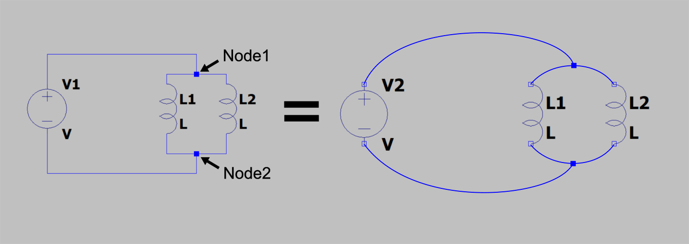
Node1 and node2 again can be defined freely. For example, you can assign a number (0, 1, 2 and so on), a letter (a, b, c and so on) or some more elaborate names, such as N001, N002 and so on. Nodes are intersection points between every 2 components in your system. Note that nodes are not corners where the same wire turns! For example, in this schematic there are only 2 nodes that connect everything together, despite the fact that visually wires are bent at different places as well.
Component value
In the netlist file for each component the last thing you need to define is characteristic value. For CENOS components (inductors) you can leave the value as a variable, for example, as L – this value will be overwritten by CENOS once you assign the circuit components in CENOS UI.
If the component is defined completely in the netlist file, such as power source or resistor, then you need to define the characteristic value such as current, voltage or resistance of the component.
Example netlist – parallel coils
For the example mentioned above, we want to define 2 coils connected in parallel. We apply 10V voltage to the voltage source with 50 Hz frequency. We position each component between the 2 nodes that are present, and define placeholder L values for both our inductors.
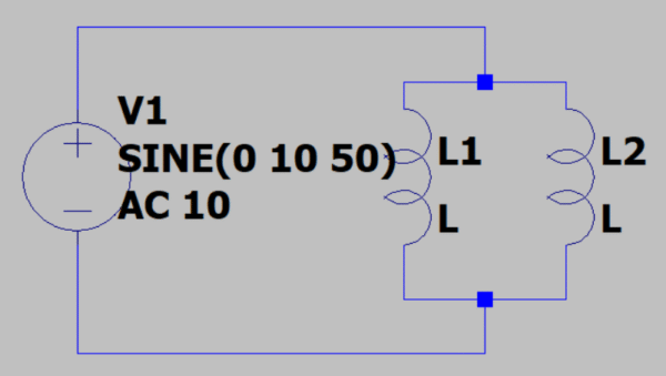
For such circuit, the netlist file would be written as:
L1 N001 N002 L
L2 N001 N002 L
V1 N001 N002 SINE(0 10 50) AC 10
.end
Notice 2 things – we need to define frequency in the netlist file, even if it will be overwritten by CENOS later on, and we need to end the file with .end.
Setup in CENOS
In CENOS create a case as usual – template, import CAD or Open CAD editor.
In SIMULATION CONTROL tab you will see a section Circuit simulation in which you can enable circuit input.
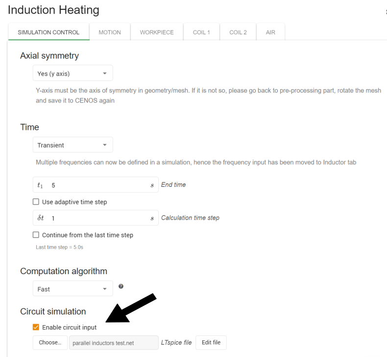
Once you enable the circuit input, you can choose a .net file to upload to CENOS.
After importing the .net file, you will see some changes in the inductor tabs. Here you now need to define the id of the component such as it is in the .net file, as well as the frequency for the inductor.

Tips & tricks
Netlist definition using LTSpice
If you prefer a more visual approach, you can use LTSpice tool to create the circuits and export the .net file.
Make sure to implement all the necessary values by right clicking on the component and inputting values – a value must be assigned to anything that is not implemented in your CAD file!
To create a netlist file of your circuit, you need to first open it in View > SPICE Netlist. This will not only show the netlist text file, but also generate it in the background where your LTSpice file is saved. You can then use that .net file and import it in CENOS. Do remember, that this is a temporary file, and will disappear once you close LTSpice file!

Results
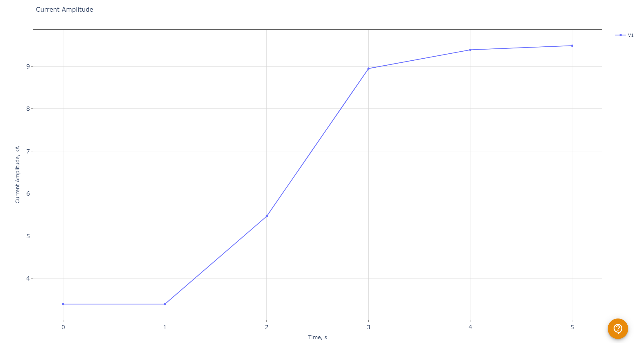
When using netlist files for calculation, in results Performance Plots section under Current and Voltage graphs you will find one output value that is measured on the power supply in your circuit. Separate values measured on inductors will come soon!
Limitations
From passive components, right now only resistors are possible to define. Capacitor and inductor support will come!
