Current density and magnetic field around high current 3-phase busbars
Electrical systems that carry high currents, especially in industrial setups, depend on components like bus bars to distribute power efficiently and safely. However, the performance of these systems is influenced by the interactions between electric currents and magnetic fields, which can lead to significant challenges in the design and operation of bus bar assemblies. The simulations shown here offer insight into these effects, specifically focusing on current density and magnetic field distribution in high-current, 3-phase bus bars.
In this post, we will break down the simulation images to provide an educational and engaging explanation for engineers who regularly use simulation software like FEA or computational electromagnetics in their work.
Simulation breakdown: current density and magnetic field interaction
The simulation visualizes current density and magnetic field interactions around high-current bus bars. These bus bars are responsible for conducting large amounts of electrical current across different phases in a 3-phase system.
Here’s a detailed breakdown of what’s happening in the two simulation images:
Image 1: understanding the color gradients and field lines
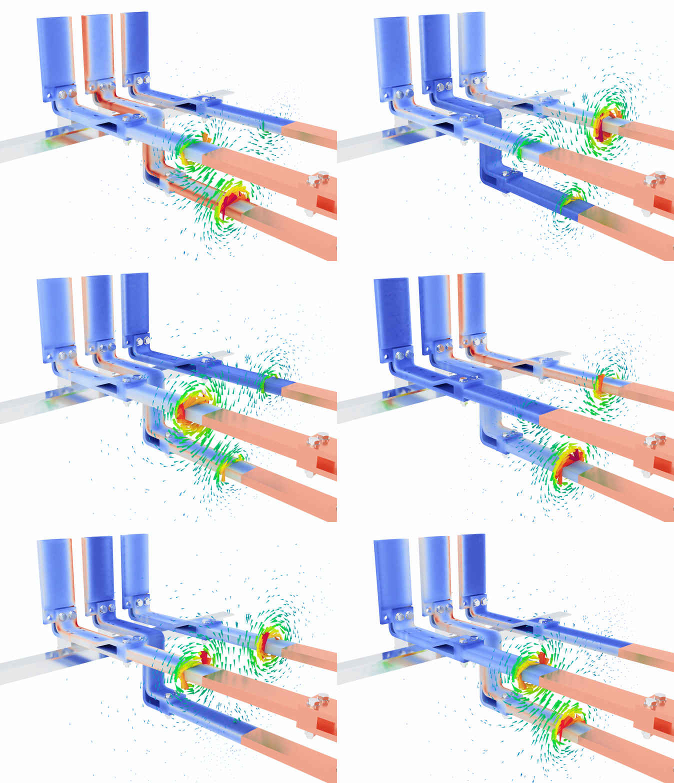
In the first image, the blue and red color gradients represent current density within the bus bars. Blue typically signifies regions with lower current density, while red indicates areas of higher current density. As the current flows through the bus bars, you can observe that the current density is not evenly distributed. This is a typical effect due to the skin effect, where alternating current tends to concentrate on the surface of a conductor at higher frequencies, leaving the core less utilized.

The green lines swirling around the bus bars represent the magnetic field generated by the flow of electric current. According to Ampère’s Law, a current-carrying conductor generates a magnetic field that encircles the conductor. Here, you can see the magnetic field lines circling each phase of the bus bar, with higher field intensities closer to the conductors and a more dispersed field further away.
- Key observation: The bus bar design must account for these magnetic fields to prevent unwanted interference or inductive coupling between phases, which could lead to efficiency loss or overheating.
Image 2: hotspots and magnetic interactions
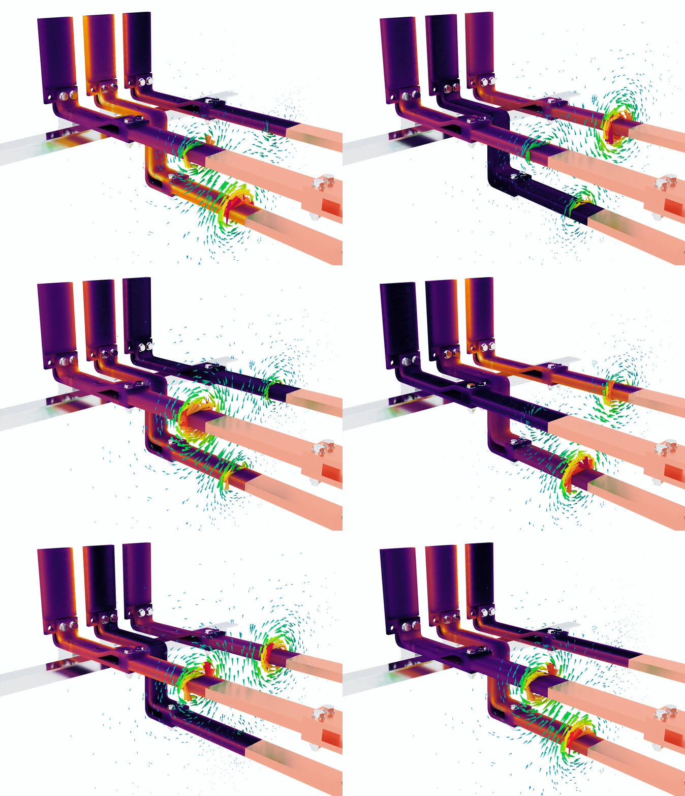
In the second image, the simulation introduces a more detailed view of heat generation through the use of a purple and yellow color gradient. This visual likely represents areas of heat concentration due to resistive losses as the current flows through the bus bars. Areas with darker purple colors have lower temperatures, while bright yellow highlights regions of higher temperature.

This is crucial because temperature buildup in a conductor not only reduces efficiency but can also lead to material degradation or even failure in extreme cases. Thermal management becomes critical in bus bar design, especially when dealing with high current loads.
The green magnetic field lines are once again visible, providing a visual confirmation that the magnetic fields interact with the surrounding space as expected. Notice how the magnetic fields still swirl around the bus bars but are also slightly more concentrated where the heat buildup occurs. This suggests that eddy currents or localized current concentrations could be influencing the thermal performance of the bus bar.
- Key observation: This simulation underlines the importance of thermal management and magnetic field control in designing bus bar systems, especially when the system operates at high currents over extended periods.
Insights for engineers
The simulations provide valuable information for engineers working on electrical distribution systems and bus bar design:
- Current density distribution: Uneven distribution of current in bus bars, as seen in the color gradient, shows the importance of using the right material and design to mitigate the skin effect and ensure maximum efficiency.
- Magnetic field interactions: The magnetic fields generated by the current flow must be carefully managed to prevent interference between the different phases. Shielding or phase separation strategies may be required, especially in high-current applications.
- Thermal management: Hotspots visible in the simulation highlight the importance of considering thermal effects in bus bar design. Adequate cooling mechanisms, such as forced air cooling or liquid cooling, might be needed in high-power applications to avoid damage and prolong the lifespan of the system.
- Eddy currents and power loss: The interaction between magnetic fields and conductive components may also lead to unwanted eddy currents, which contribute to power loss and overheating. Simulation helps visualize these potential issues before physical implementation.
Conclusion
This simulation highlights the complexity of high-current, 3-phase bus bar systems, where current density, magnetic field interaction, and thermal effects all play a critical role. By utilizing simulation software, engineers can optimize the design and materials used in bus bars to ensure both safety and efficiency. Ultimately, these findings reinforce the value of simulation tools in predicting real-world performance and preventing costly design mistakes.


