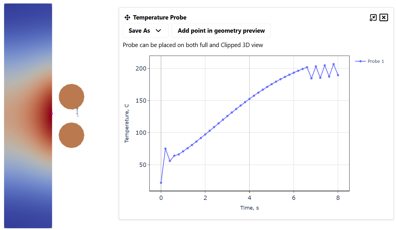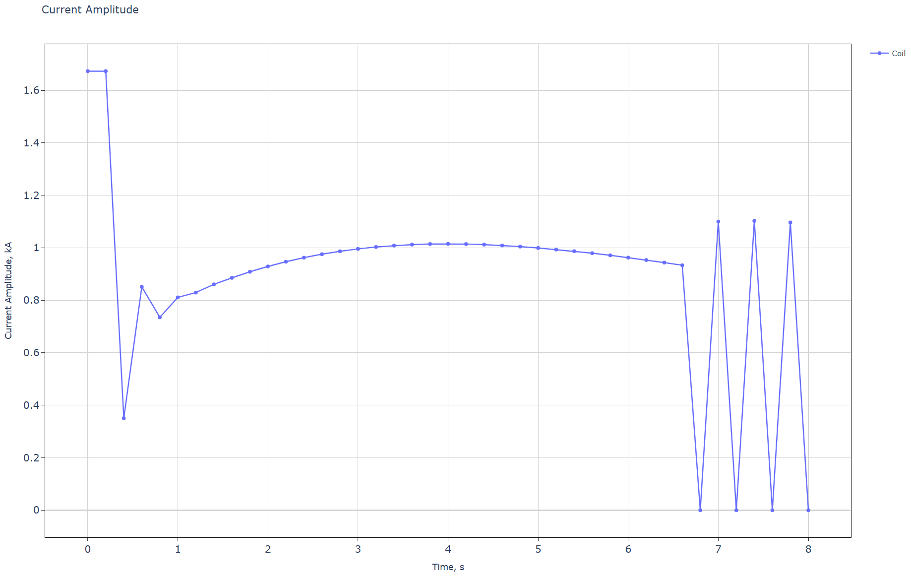
PID control
In some induction heating or hardening systems maximum temperature control is crucial to avoid local material deformations or even cracking. To deal with that, PID controllers together with thermocouples or infrared cameras are used to monitor live temperature and adjust the applied power to the process to avoid overheating the material. In this article we will take a look at how to define PID controller in CENOS Induction Heating simulation software.
How to enable it
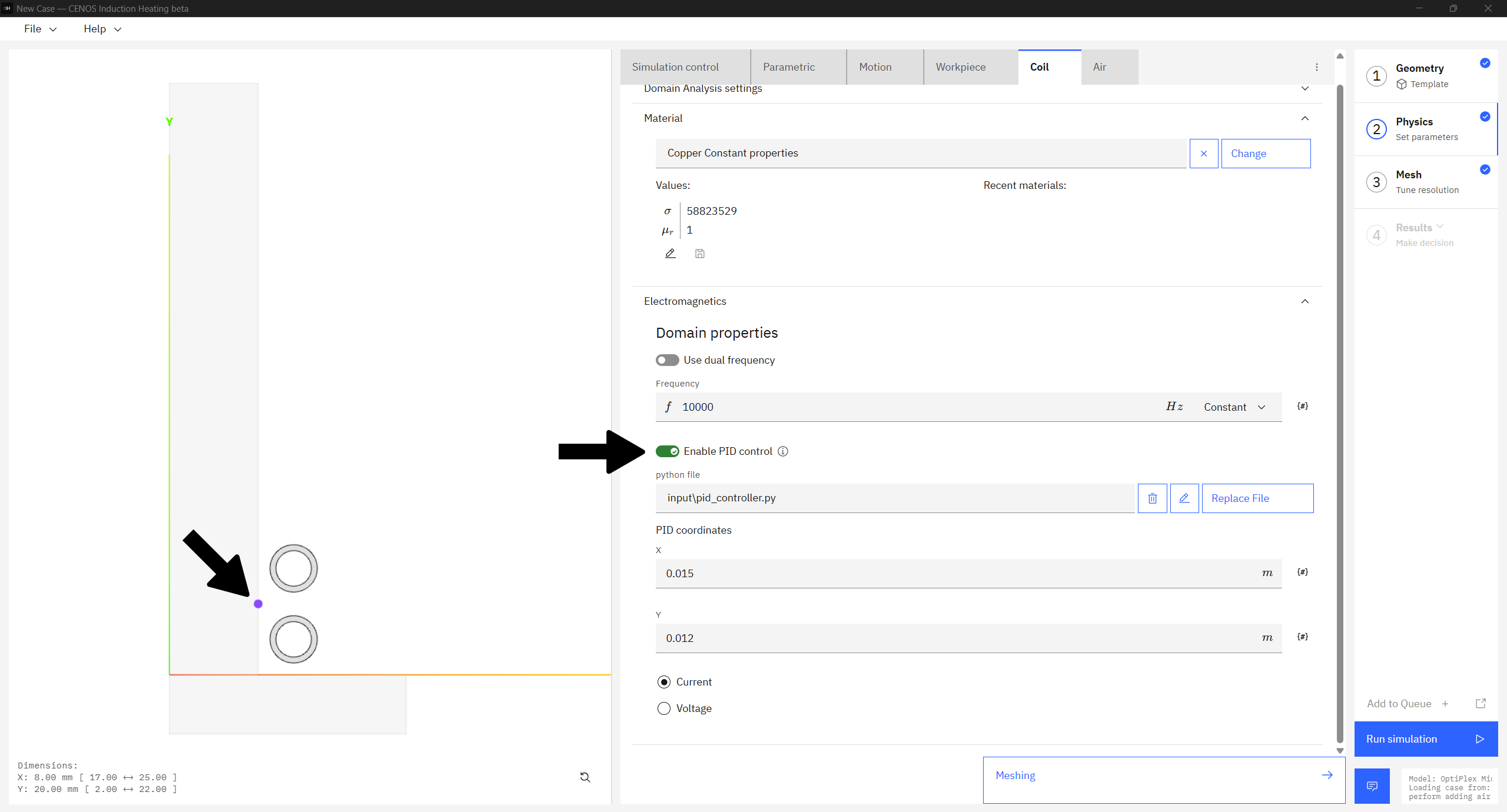
PID control can be enabled in Inductor tab in physics. Switch on the Enable PID control toggle, select the Python script for your PID controller, define coordinates for the control point (purple point in geometry preview) that the PID will use to measure temperature, choose which type of control, current or voltage, you will use, and you are all set!
How it works
Since there are a lot of different ways how a PID controller can behave, CENOS offers a fully customizable script that controls the behavior of your PID controller and that you can adjust to match your system exactly.
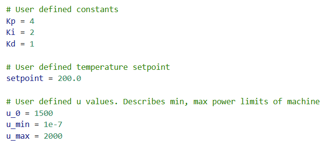
Below you can find an example script that can be used as is or adjusted if necessary. Script is controlled by 3 user inputs:
- Constants (Kp, Ki, Kd) – Proportional, Integral and Derivative components that control PID controller response/sensitivity to increasing temperature at the measurement point
- Temperature setpoint (setpoint) – temperature above which PID controller is not allowed to go; measured at a point defined in CENOS UI
- Applied current/voltage limits (u_0, u_min, u_max) – define the range of your power supply within which the applied current or voltage can fluctuate
Results
Once everything is set up, the script will control the current/voltage input based on the temperature dynamics at a point. Depending on the constant values, temperature response can be rougher or smoother, which can result in sudden changes in temperature and voltage/current/power values used in the simulation.