Parametric Studies
When designing an RF system, running parametric studies is really helpful because it lets you try out different design variables and find the ones that give the best performance. This article will show how to create parametric studies in CENOS : RF using two different approaches:
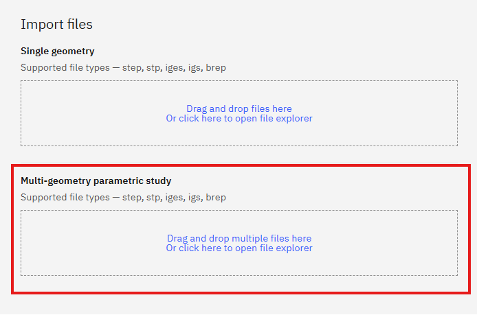
Import CAD
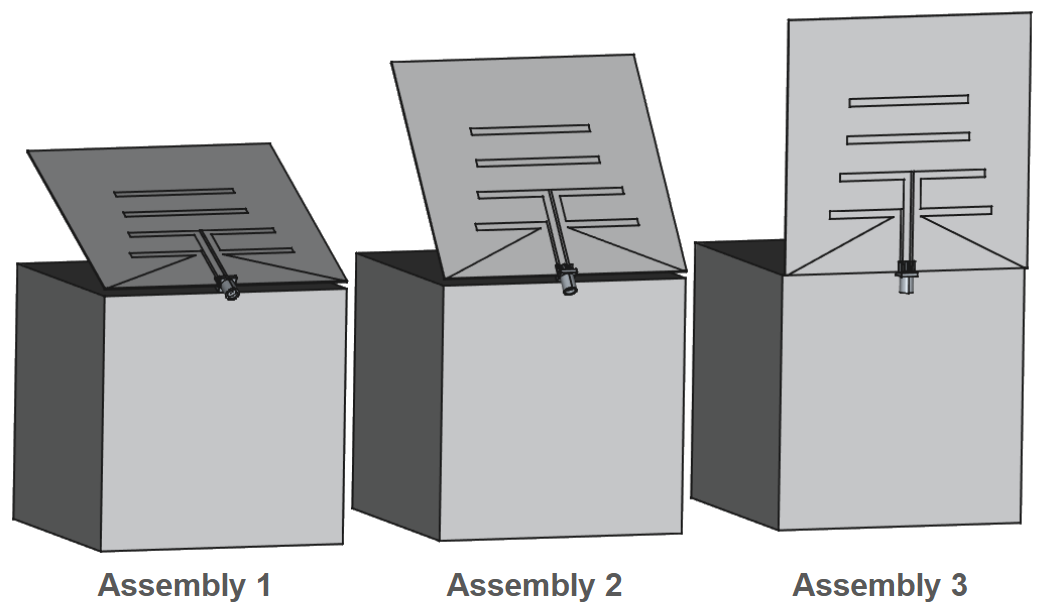
With this approach, multiple CAD files representing the same geometry but with different dimensions can be imported at once. After loading the files, you only need to define the roles and physics for one of the cases.
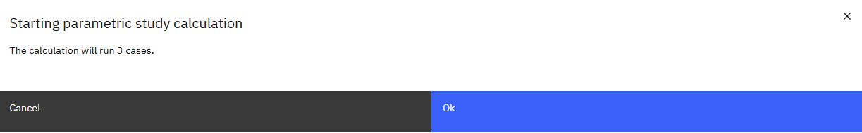
When the simulation is run, a separate simulation case will be automatically created for each imported CAD model, allowing the results to be evaluated and compared efficiently.
Import eCAD
Similar to CAD files, multiple projects can be imported using Gerber files when the PCB geometry is consistent across all models and only the dimensions differ. After selecting the From Gerber approach, the Multi-geometry Parametric Study option becomes available.
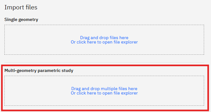
The files for each model must be stored in separate folders and meet the following requirements:
- Each folder must contain the same number of files.
- File names must match exactly across all folders.
- Each corresponding file must represent the same PCB part in every folder, not a different one.
After starting the simulation, the corresponding parametric study cases are automatically generated for each model. Once the calculations are complete, the results can be reviewed and compared to better understand the impact of the dimensional variations across the different designs!
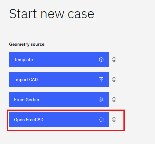
CAD editor
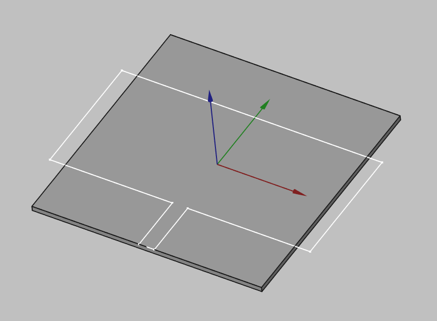
By using the integrated CAD editor (FreeCAD), the geometry can be created from scratch and fully parameterized. This allows the values of design variables to be modified easily!
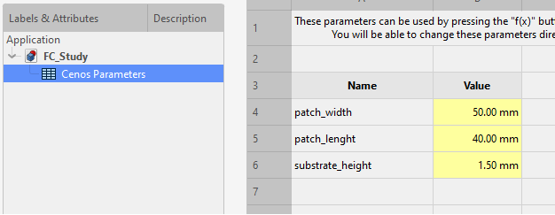
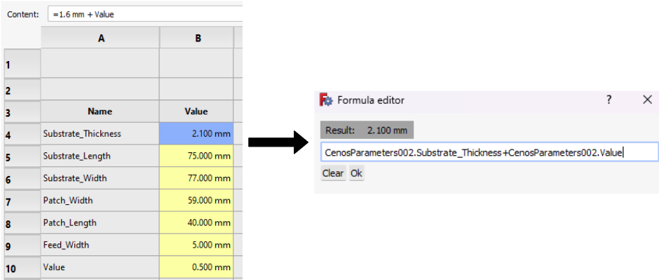
You can define parameters in the Cenos Parameters spreadsheet where you can use various units and/or mathematical equations for the values.
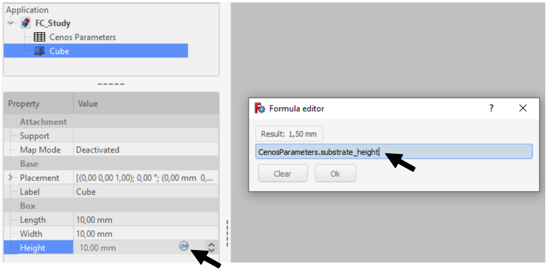
To use these parameters, click the Formula Editor button in the value field and then enter Cenos.Parameters.name.
Once you have finished working on your model and assigned all the parameters you are interested in, you can send the geometry to CENOS, where in the Physics section you will be able to start the parametric study.
Getting the geometry to CENOS
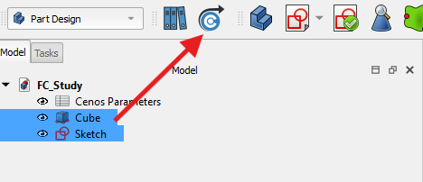
To send your finished geometry to CENOS, you have to:
- Select all final objects in the tree view.
- Click Send Geometry to CENOS.
As geometry is being sent to CENOS, the FreeCAD study will be automatically saved in the simulation folder, so you can close it.
How to use Parametric Study?
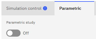
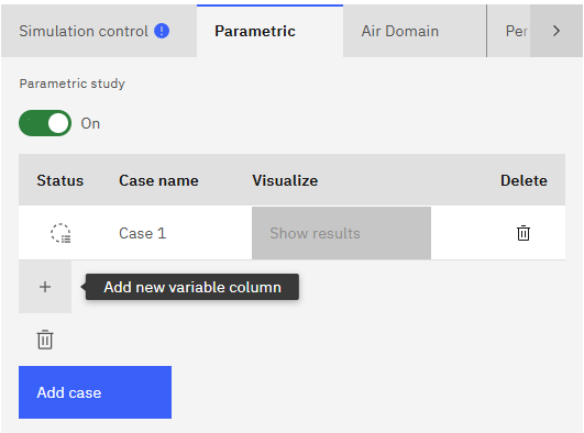
Once you have sent your geometry to CENOS and are in the Parametric tab, you will need to enable the parametric study.
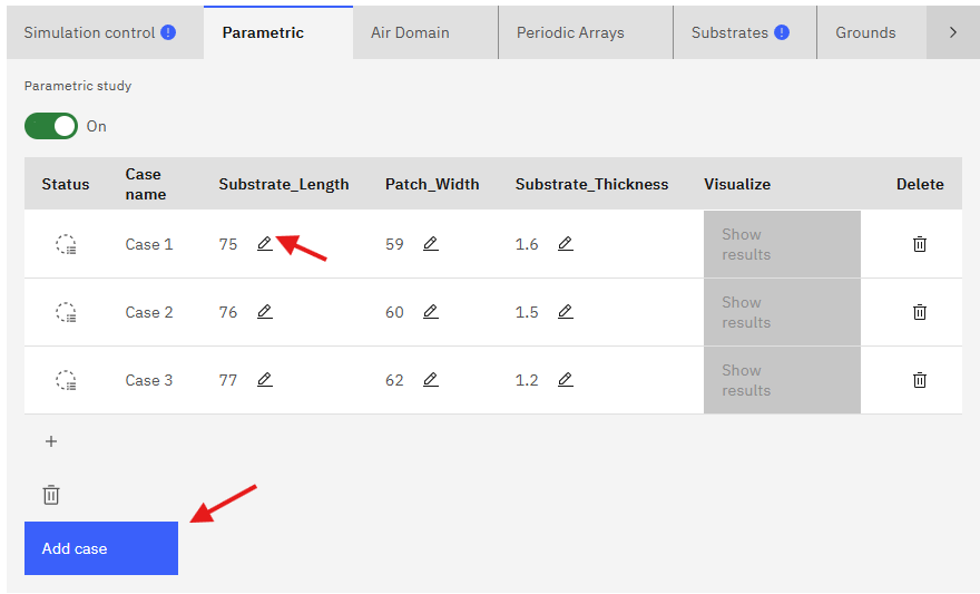
The parameters you have previously defined will appear in a new window, you can add one or more parameters! You can also add as many cases as you need to simulate – just click Add case and a new case will be created.
When you have finished making the necessary adjustments, you can continue with the usual workflow in the other tabs.
Limitations
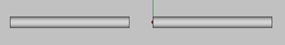
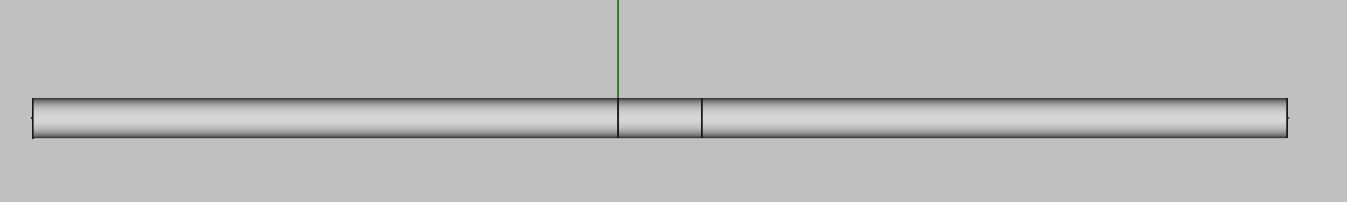
Geometry overlapping
By changing the parameter values, geometry can become non-physical, i.e. elements can overlap each other or sketches can be left out of a solid surface. It is necessary to avoid these situations so that the simulations work properly and the results are obtained without any inconvenience. Make sure that your geometry has the necessary constraints and that the parameter dimensions are physically possible.
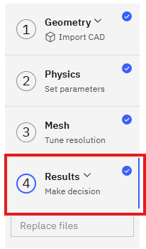
How to access the results of the Parametric Study?
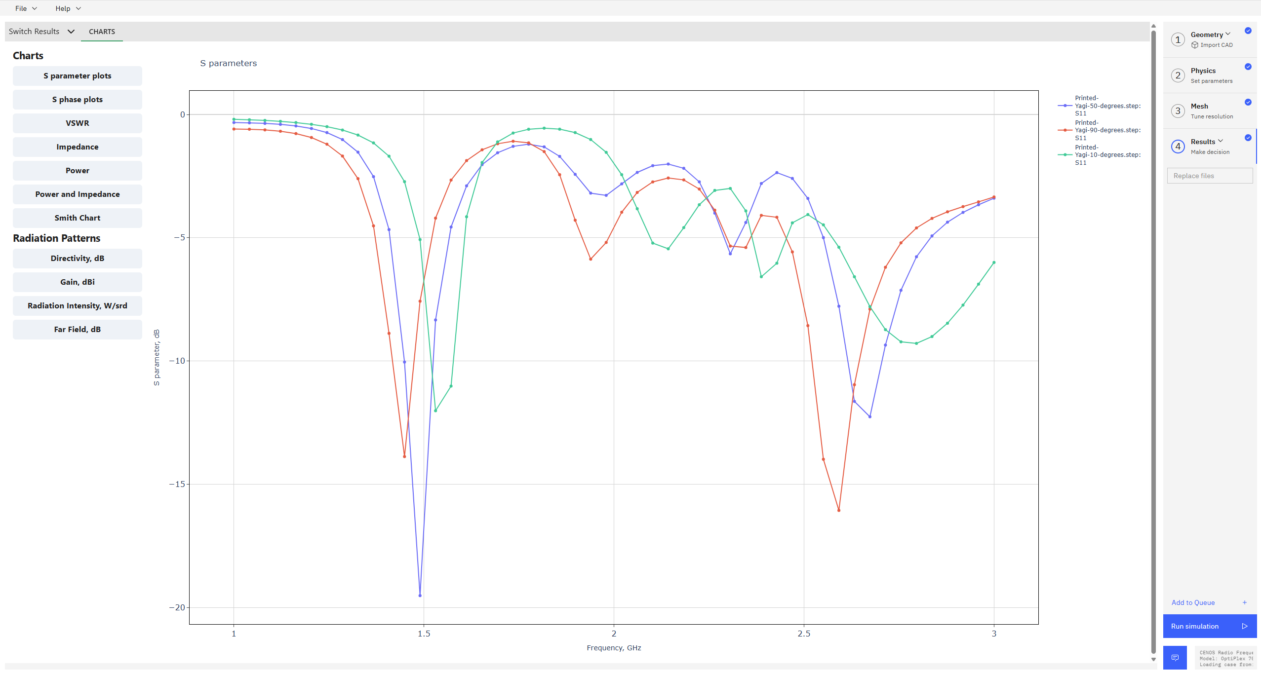
Once your simulation has finished computing, the results will be displayed automatically. You can access the charts for all cases within a single window, allowing you to directly compare the performance of designs with different dimensions.
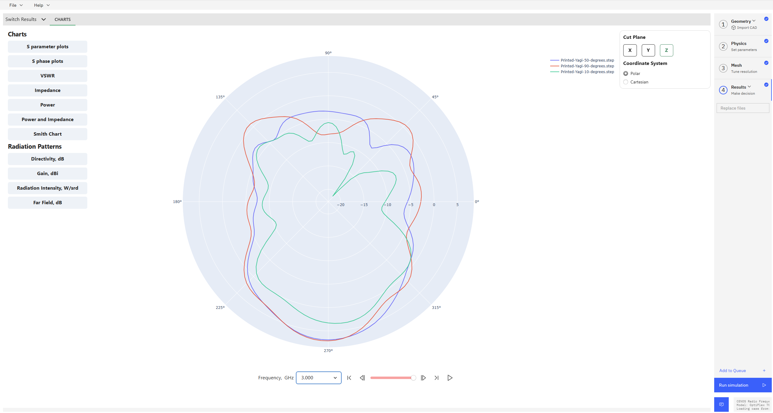
Similarly, the radiation patterns for all cases can be viewed in 2D, in both polar and cartesian coordinate systems, for each calculated frequency. This setup provides a clear and convenient way to analyze and evaluate the performance of each configuration.
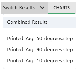
You have the option to switch between combined results and the individual results of each case:
- In the Results window, click on the Switch Results tab in the upper left corner to display a list of all computed cases.
- Clicking on the Results section on the right side menu will take you directly to the combined results view, allowing for a convenient overview and comparison of all cases.