Setting up sliced cases
With CENOS it is possible to simulate a symmetrical part of an object (half, quarter, slice, etc.), which gives valid results that can be mirrored to represent the whole geometry, but in the same time significantly decreases the calculation time.
To take into account the symmetry of the object and set up the simulation properly, symmetry boundary conditions (BC) are used, through which the position of magnetic field lines in respect to symmetry planes are defined.
Symmetry conditions should be defined for every domain in the simulation, e.g. not only for the workpiece slice, but for the air and flux concentrator domains as well!
Symmetry boundary conditions
When a current is flowing through a wire, it creates a magnetic field around it, with magnetic field moving around the current flow direction.
In induction heating when complex inductors are used and an object is placed within this magnetic field, some faces of the object are parallel to the magnetic field lines, while other are normal to them.
By knowing how the magnetic field lines are positioned, we can understand their position in respect to different surfaces or boundaries of our geometry.
Based on this fact, two symmetry boundary conditions are introduced – Flux Parallel and Flux Normal.
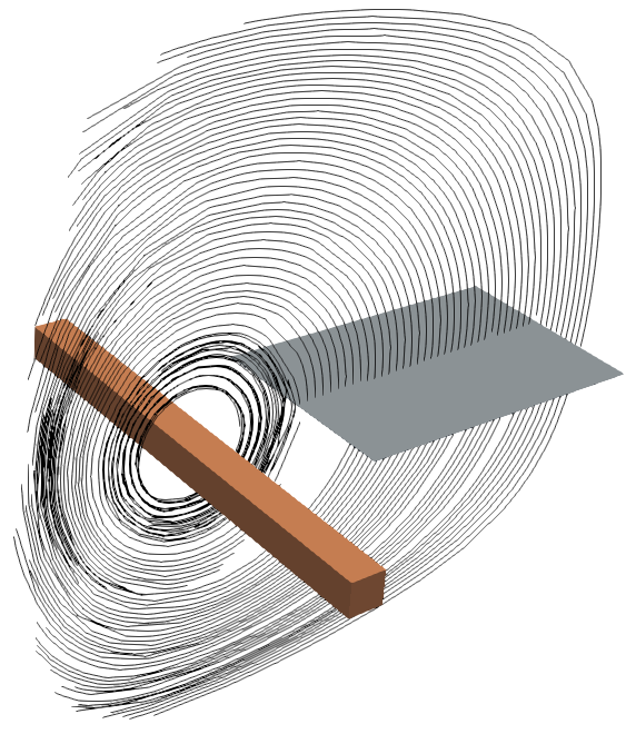
Flux parallel
Flux parallel BC defines that the magnetic field lines are parallel to the surface, meaning that these lines do not cross the plane.
In this example a straight inductor is generating a magnetic field, which lines are positioned parallel to a plane and are going along the side of it.
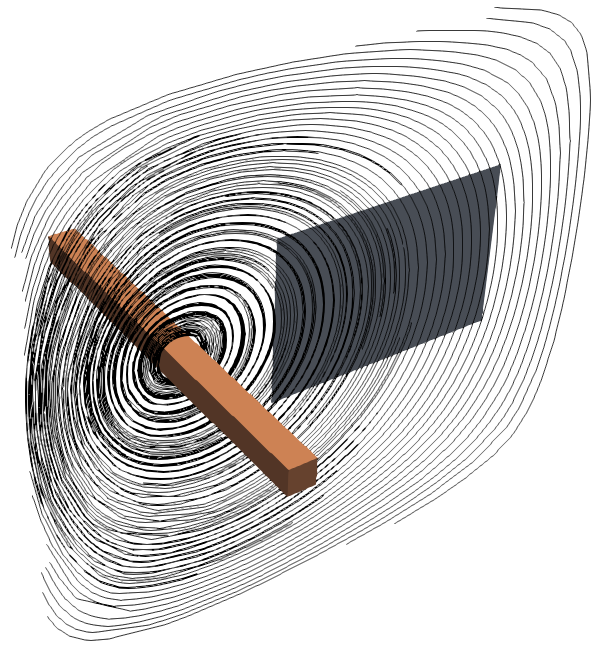
Flux normal
Flux normal BC defines that the magnetic field lines are normal to the surface, meaning that they go directly through the plane.
In this example a straight inductor is generating a magnetic field, which lines are positioned normal to a plane and are going straight through it.
Use of Symmetry BC
Symmetry BC are used to simulate only a small part of the whole geometry, significantly decreasing the calculation time while producing the same accurate results as full geometry cases.
In the next examples we will demonstrate the outer boundary definitions for different symmetry cases.
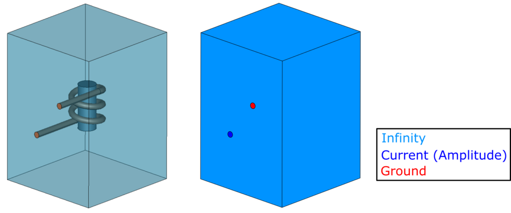
Half
Most of the induction heating systems are at some level symmetrical and can be sliced in half while preserving the accuracy of the results.
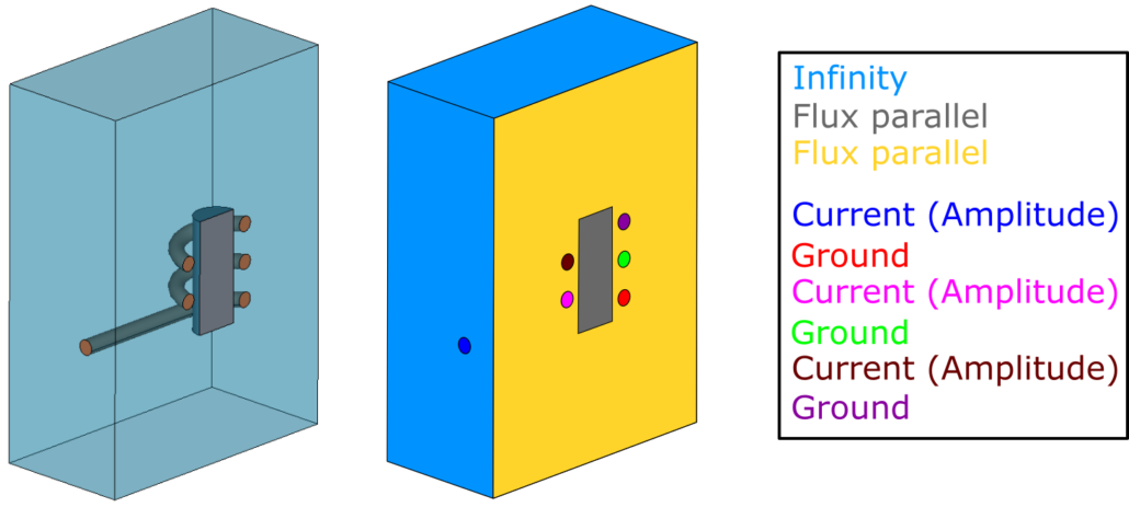
In this example we will look at a simple multi-winding coil and a cylindrical billet system. For full system on the outer boundaries we define Current (Amplitude) and Ground on the terminals, and the outer air faces with Infinity.
If we cut the geometry in half, we need additional boundary conditions to define the symmetry cut. We need to define the new symmetry planes for air and workpiece with Flux parallel, and for each half of the winding we need to create new terminals, on which we will define Current (Amplitude) and Ground.
Symmetry boundary condition for this case is Flux parallel, because the inductor parts which go into the plane creates a magnetic field parallel to these planes.
Quarter
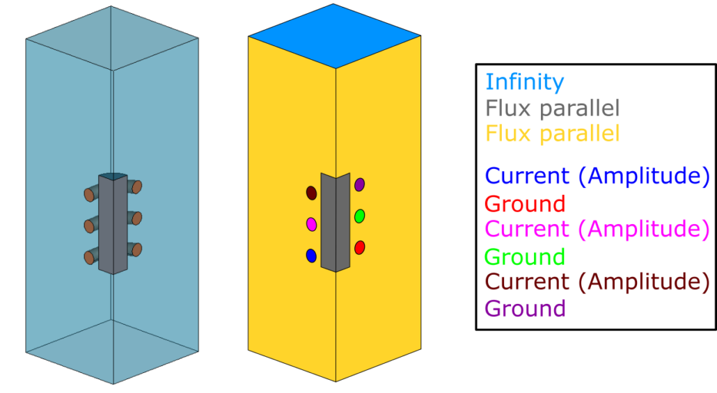
You can use the symmetry of your geometry even more and simulate not half, but a quarter of your system.
We will use the same geometry as we did for the half symmetry example, but this time we will set up only quarter of it.
The boundary conditions used are exactly the same as for half symmetry – define the symmetry planes for air and workpiece with Flux parallel, and for each quarter of the winding we need to create new terminals, on which we will define Current (Amplitude) and Ground.
Symmetry boundary condition on both symmetry planes are Flux parallel, because the inductor quarters which go into the plane creates a magnetic field parallel to both symmetry planes.
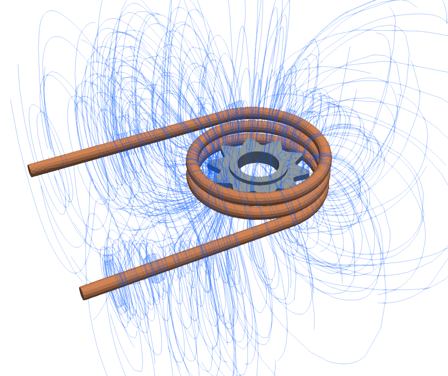
Slice
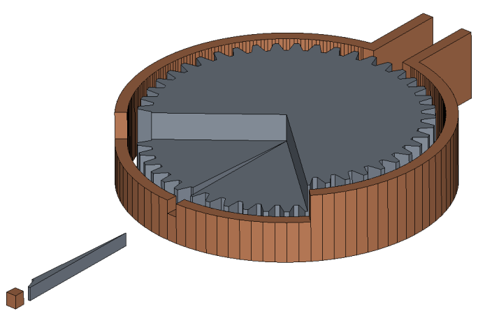
For geometries with some level of axial symmetry you can simulate only a slice.
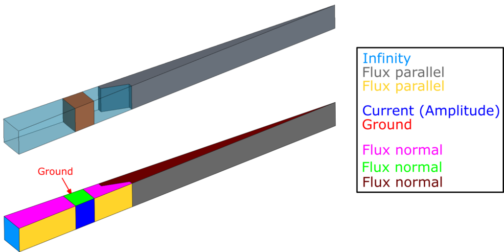
In the example below a half slice of the gear tooth has been cut out, and symmetry conditions need to be used not only for parallel, but for normal symmetry as well (notice that the slice is only a part of the full system height).
Parallel symmetry BC’s are exactly the same as in the previous examples – define the symmetry planes for air and workpiece with Flux parallel, and for inductor slice create terminals, on which to define Current (Amplitude) and Ground.
We also need to define the normal symmetry (part of the full height of the system), which is why for inductor, air and workpiece top and bottom faces Flux normal is defined.
If the inductor is sliced in a way that reduces its cross-sectional area compared to real life, the current value must also be rescaled proportionally to the new cross-sectional area. This kind of setup is used rarely and in most of the cases current do not need to be rescaled.
How to choose correct inductor input value?
- Current: Because current is the same in every cross section of the inductor, you can input the same value as is used in real setup. No need to recalculate anything.
- However, if the inductor is sliced in a way that reduces its cross-sectional area compared to real life, the current value must also be rescaled proportionally to the new cross-sectional area.
- Voltage: Voltage depends on the geometry, so it needs to be recalculated based on the slice angle.
- Example: If your input is 1000V for the whole system, then for 180deg slice, you will input 500V -> 1000*180/360=500
- Power: Power in CENOS is defined as the total generated active power of the system (inductor + workpiece) and it also depends on the slice angle. Recalculate it based on the slice angle.
Multiple Inductors
If the simulation involves multiple inductors, CENOS calculates the same current value for each inductor to meet the desired total power in the system.
Rotation
If you want to simulate rotation using Complex Motion, Symmetry Boundary Conditions cannot be applied and you will need to calculate a case with full geometry.
Additional information
If you want some more practice with setting up sliced cases, please refer to this tutorial article.
If you encounter any issues or want to learn more about how to improve your simulations in CENOS, do not hesitate to contact us through the live support chat inside the CENOS application or email us at support@cenos-platform.com.
