Inductor input types – power, voltage or current
Selecting the appropriate input type for your inductor—current, voltage, or power—depends on your system configuration and simulation requirements.
By understanding the constraints and behavior of each input type described in this article, you can select the most suitable approach for your simulation needs.
Additionally, we provide recommendations for what to do if your simulation results do not match your expectations.
Choosing the correct input type
Selecting the appropriate input type for your inductor—current, voltage, or power—depends on your system configuration and simulation requirements.
If the total power consumed by the system (inductor + workpiece) is known, it can be set as the input.
Setting current as the input is often the safest choice. You can directly specify the current for each inductor.
Voltage input also is a flexible option for systems with multiple inductors. Different voltage values can be assigned to each inductor.
Using power as input
If the total power consumed by the system (inductor + workpiece) is known, it can be set as the input. However, there are important considerations:
- Cenos regulates the total power by adjusting the current in the inductor.
- The process involves initially applying 1A current, calculating the system’s power, and then determining the required current to achieve the desired power through proportional scaling.
- Multiple Inductors:
- If the simulation involves multiple inductors, Cenos calculates the current for each inductor to meet the desired total power.
- Restriction: Power control cannot be used if the inductors require different power values, as this also implies differing current values.
- Power Transfer Efficiency (impedance matching)
-
- If the system’s efficiency is less than ideal, you may notice that the simulation results show higher temperature values for the workpiece or a hardened profile that is too wide or deep. To maximize efficiency and ensure accurate results, proper impedance matching between the source and the load should be performed. This ensures optimal power transfer and minimizes energy losses in the system.
- One of the reasons why power in the coil is lower than in the generator are the different impedance values of the load (coil) and the source (generator). Impedance is calculated as:
Z=sqrt(R2+XL2+XC2)XL=2πfLXC=1/2πfC
-
- where L – inductance, C – capacitance, R – resistance, f – frequency, XL – inductive reactance, XC – capacitive reactance.
- The maximum power-transfer theorem says that to transfer the maximum amount of power from a source to a load, the load impedance should match the source impedance.
Zload=Zsource
What to do if results are not as expected
If the power input in CENOS results in excessively high temperatures or an overly deep hardening profile, it likely indicates unknown power losses in the system. To determine the actual power, the most accurate method is to measure the current or voltage directly on the coil and use this value. If measurement is not possible, CENOS can help estimate the power that produces the expected results (e.g., temperature or hardening profile) and based on that get the systems efficiency.
Active vs. Apparent power
Often when looking at the results, you will notice that if you multiply current and voltage from results, you will not get the power value that is displayed in the results. That is because CENOS operates with Active Power, which is calculated slightly differently.
When you multiply I*U, the result is apparent power. In CENOS we input active power, which is a component of the apparent power. Active power is integral sum of joule heat density fields in all domains. It is the part of power that does the heating and which is related to material resistance. It is calculated as P=I^2⋅R.
Apparent power, is calculated as P=U⋅I. In reality, this power consists of two components: active (real) power and reactive power. If a system is purely resistive, only active power exists. However, in inductive systems inductive reactance is present. Therefore, instead of resistance R, we must use impedance Z, which represents the total opposition to AC current. From the same voltage and current values, impedance can be found as Z=U/I. Impedance has 1) real part, which is the resistive resistance R, and 2) imaginary part, which is the inductive reactance X_L. From inductive reactance we can also get reactive power value as P_react = I^2⋅X_L. Apparent power can also be calculated as vector sum of active and reactive power components: P_apparent = sqrt(P_act^2+ P_react^2)
When is power control not applicable?
Power control cannot be used when the simulation involves multiple inductors with different power or current requirements. In such cases, Cenos calculates a single current value for all inductors, which is incompatible with varying power needs.
Using current as input
Setting current as the input is often the safest choice. You can directly specify the current for each inductor.
What to do if results are not as expected
Unknown resistances in the system may reduce the current reaching the inductor. To measure the actual current, use a Rogowski coil compatible with your system’s current and frequency. These coils are easy to find online. The Rogowski coil detects the inductor’s magnetic field, generating a voltage that is converted into the current value.
Using voltage as input
Voltage input also is a flexible option for systems with multiple inductors. Different voltage values can be assigned to each inductor.
Important Note:
Voltage inputs must consider losses in the system. For instance, if the voltage is measured at the generator or far from the coil, there could be a voltage drop along the connection.
What to do if results are not as expected
Voltage-controlled simulation is sensitive to the geometry used. When applying voltage input, remember that all parts of the system contribute to voltage drop. For example, 2D simulations typically exclude terminals, busbars, or other connecting parts. To accurately simulate the heating process, adjust the input voltage to reflect the value directly applied to the inductor, excluding the rest of the system.
In 3D simulations, the situation is similar. While most setups include some connection parts, these are often much shorter than in reality. In such cases, the voltage input should also be adjusted accordingly.
How to adjust voltage input
If a voltage-controlled generator is used, it means that the voltage from the generator is applied to the whole system together. The whole system is an inductor together with any kind of busbars that connects it to the generator. In most cases we do not want to include the busbars at their full length in the simulation to make the simulation simpler and faster. Not including the total length of busbars means that we need to adjust the voltage input value in the Cenos. In this article we explain why is that and how to adjust it.
Example of a voltage controlled system
Any system where coil is connected to the generator actually can be looked as a circuit with coil and two resistances. If the connecting parts between generator and coil are short, it means that they have relatively low resistance and their impact on the system is minimal. However, if these parts are not short, their effect on the system becomes significant and must be accounted for.
Lets look at the generator that gives a constant voltage of 10 kV. The coil has its inductance L and impedance Z, connecting parts have resistance R1 and R2.
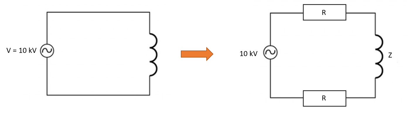
The resistance of each busbar can be calculated
R=ρl/A
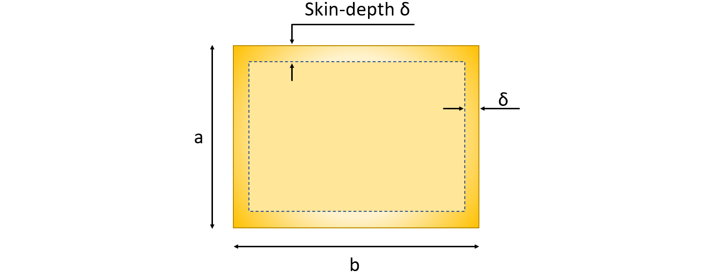
where ρ is resistivity [Ohm⋅m], l – length of the busbar, A – area, where the current is flowing. To calculate area A, you need to find the skin depth in which the current is flowing and calculate this area. For example, if the inductor is rectangular with side lenght a and b, then area A is
A=2δa+2δb−4δ2
Simulating the complete setup
Simulate the complete setup, including all connection components, to determine the voltage drop in these parts. This process requires only one simulation step and an electromagnetic analysis (thermal analysis can be skipped).
Here are steps on how to do it:
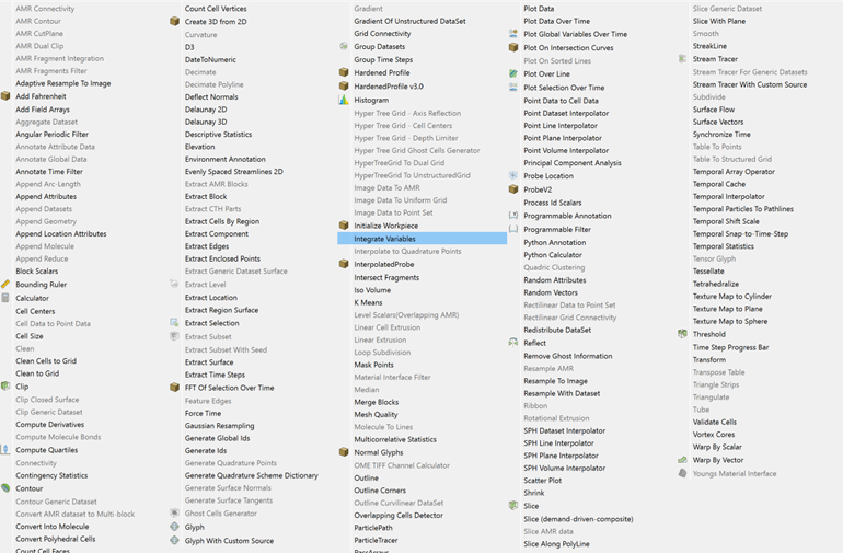
- Open the simulation results in ParaView and select inductor domain in the Pipeline Browser.
- Apply the “Integrate Variable” filter to the inductor domain. You can find it under Filters>Alphabetical>Integrate Variable. This filter sums values for all the nodes for each of the field.
- Find integrated Joule heat for the whole inductor, note the value (Q_total).
- Make a clip where only inductor terminals are visible. Integarte joule heat for this part (Q_terminals).
- Calculate the proportion of Joule heat in the connection parts compared to the total system. The voltage drop proportion is the same.
Q_terminals/Q_total = V_terminals/V_total - Use the following formulas to calculate the voltage drop across the terminals
- Use this adjusted voltage value in simulations without including the connecting parts.
V_input = V_total - V_terminals
