Defining thermal cooling processes
Accurately defining the cooling process is essential for simulating induction heating. Cooling typically involves two mechanisms: radiation and convection.
- Radiation losses:
- Dominates when the induction heating process occurs in a vacuum or under very low pressure, as no medium exists to facilitate convection.
- At high temperatures, radiation becomes more dominant with increasing surface temperature.
- Radiation is defined by the emissivity coefficient.
The radiation cooling rate is determined by the Stefan-Boltzmann law:
Q=ϵ⋅σ⋅A⋅(Tworkpiece^4−Tamb^4)
Where:
- Q: Heat lost due to radiation (W).
- ϵ: emissivity of the workpiece surface (dimensionless, 0 to 1).
- σ: Stefan-Boltzmann constant (5.67×10⁻⁸ W/m2K4).
- A: Surface area of the workpiece (m²).
- Tworkpiece: Absolute temperature of the workpiece (K).
- Tamb: Absolute ambient temperature (K).
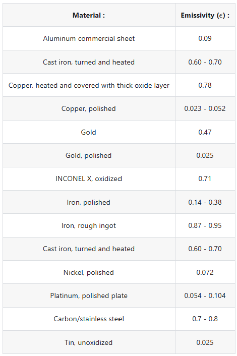
The emissivity of a material depends on both the material itself and its surface roughness. Emissivity values for commonly used materials are provided in the table below.
- Convection Cooling:
- Becomes significant in most other cases where a surrounding medium (e.g., air) is present.
- In CENOS, convection is defined by the heat transfer coefficient (measured in W/m²K), which describes how efficiently energy is lost through the surface of the workpiece. It varies based on the material properties, surface conditions, and the cooling medium.
The energy lost due to convective cooling is defined as:
Q = h*A*(T - T_amb)
Where:
- h: Heat transfer coefficient (W/m²K).
- A: Surface area of the workpiece (m²).
- Tworkpiece: Temperature of the workpiece (°C or K).
- Tamb: Ambient temperature (°C or K).
- Q: convective losses (W)
Ambient Temperature:
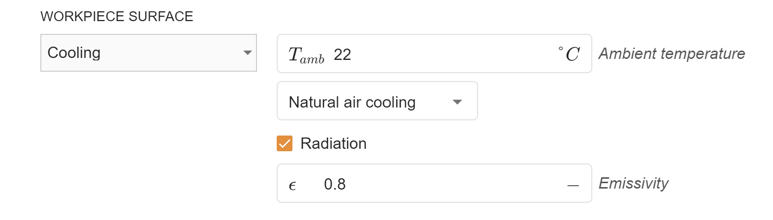
A larger temperature difference between the hot workpiece and the ambient environment increases the cooling rate. Default is room temperature (22°C).
Air cooling
In natural air cooling h is around 10 W/m2K, this is the value that is used when Natual air cooling condition is applied.
Forced cooling (quenching)
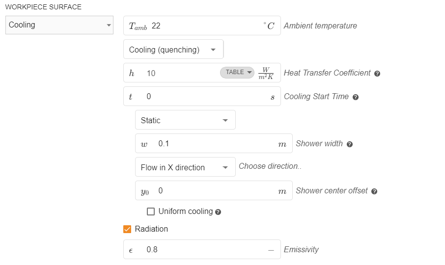
If induction heating process involves quenching, it can be defined under the boundary condition settings under “Cooling“ by selecting “Cooling (quenching)“ option.
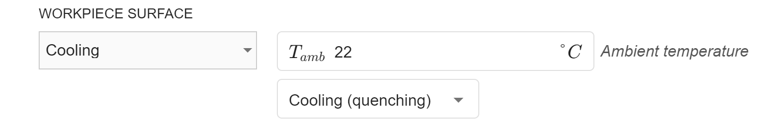
Next you can set the cooling start time. This feature is particularly useful if quenching is a separate process that occurs after the heating phase is completed.
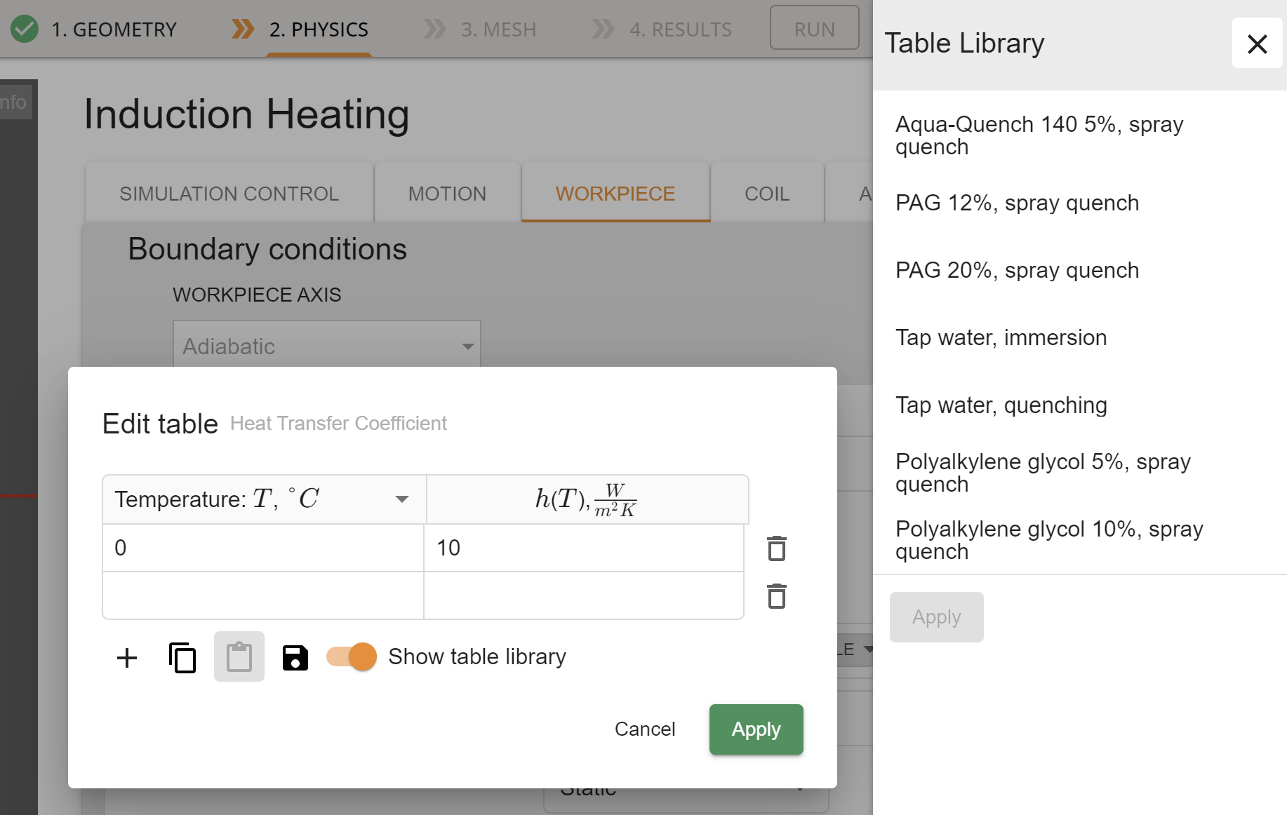
Quenching liquids have heat transfer coefficients that vary with temperature. To define this accurately, select the “Table” option for the h input field. Use the pre-defined heat transfer coefficient tables available in the Cenos library. These tables provide values for commonly used quenching liquids. Alternatively, you can input custom heat transfer coefficients if your quenching liquid is not included in the library.
Quenching shower position and motion
The next step is to define the position and motion of the quenching shower.
Static Shower Configuration:
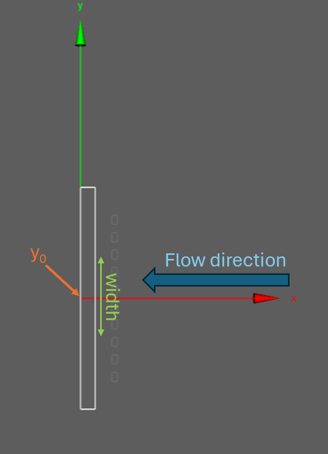
- If the shower is stationary, you need to specify the flow direction.
- For example, in a 2D case where the shower is applied to a surface parallel to the y-axis, the flow direction would be parallel to the x-axis.
Shower Parameters:
- Set the shower width
(w)and the position(y0)to define the area affected by the quenching shower. - In Cenos, these parameters are configured directly in the simulation setup interface.
This configuration ensures accurate representation of the quenching process in the simulation.
Define quenching shower motion
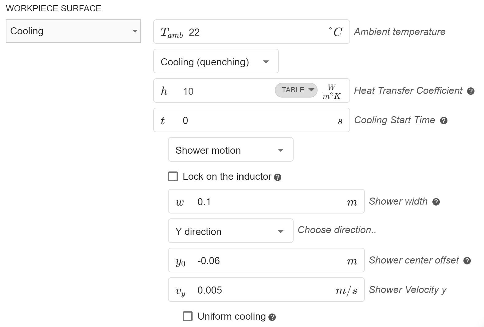
To define the motion of the quenching shower, select the “Shower motion” option.
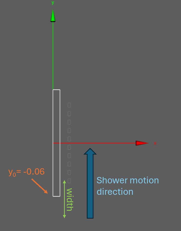
- Defining Motion Direction:
Specify the direction in which the shower moves. The quenching will occur in the plane perpendicular to the shower’s motion. - Completing the Setup:
Set the following parameters:- Start position: Defines the initial location of the shower.
- Velocity: Specifies the speed of the shower’s motion.
Example Configuration:
In this example, the shower moves along the y-direction, starting at y0=−0.06m with a velocity of 0.005 m/s.
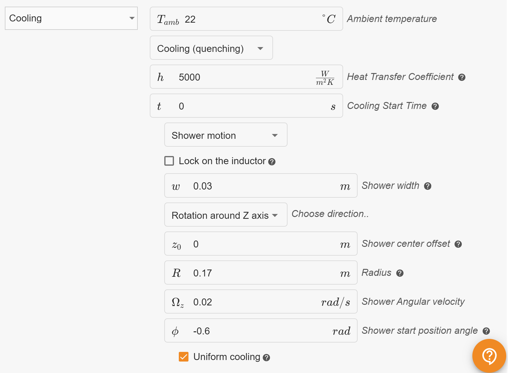
Rotational cooling
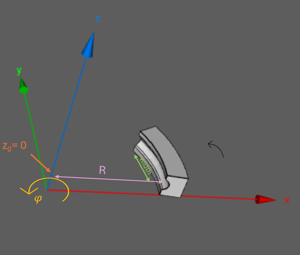
Rotational cooling can only be defined around the z-axis and is mathematically described in a cylindrical coordinate system. To define rotational cooling in a 3D case, the following parameters need to be set:
Parameters:
z0(Shower Center Offset):
Specifies the offset of the shower center along the z-axis, relative to the middle of the surface where cooling is applied.- If
z0 = 0, cooling will be applied at the center of the surface in the z-direction, regardless of the object’s position relative to the coordinate system center.
- If
R(Radius):
Defines the radial distance from the z-axis to the surface where cooling is applied.Ω_z(Rotational Velocity):
Represents the angular velocity of rotational cooling, measured in radians per second (rad/s).φ(Initial Shower Angle):
Specifies the initial angle in the xy-plane where cooling starts.- By default,
φ = 0, which means cooling begins along the x-axis. Negative values shift the starting position clockwise.
- By default,
Example Configuration:
z0 = 0 m:
Cooling is applied in the middle of the surface along the z-axis.R = 0.17 m:
Cooling is applied at a radial distance of 0.17 meters from the z-axis.Ω_z = 0.02 rad/s:
Cooling motion occurs counter-clockwise at a velocity of 0.02 rad/s.φ = -0.6 rad:
The cooling start position is shifted by -0.6 radians, moving the initial application point clockwise.
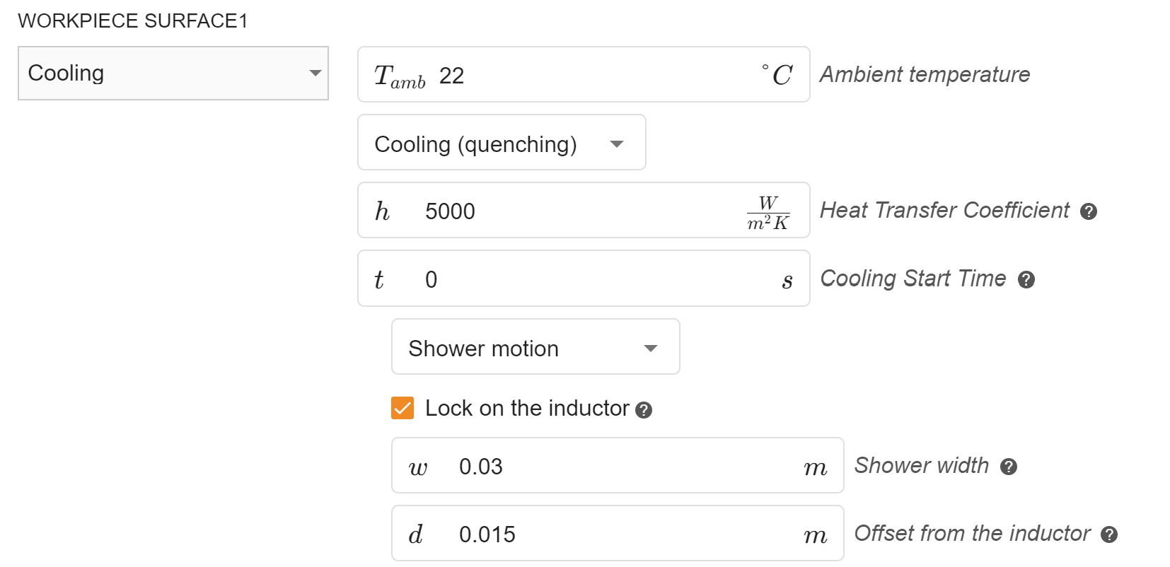
Lock on the inductor
This functionality is designed for cases where complex motion is applied to the workpiece or inductor.
When enabled, the cooling shower is automatically positioned to follow the inductor, maintaining a specified offset. The motion direction of the cooling shower is implicitly derived from the motion direction of the inductor.
To configure this feature, set the cooling shower offset (d)—the distance between the inductor and the cooling shower.
This ensures synchronized movement between the inductor and the cooling system, simplifying setup for dynamic processes.
Note: The lock-on functionality for the inductor cannot be used simultaneously with rotational motion.
Uniform cooling
By default, the cooling shower strength follows a normal distribution, meaning the cooling is strongest at the center of the shower and gradually decreases toward the edges.
If the “Uniform Cooling” option is enabled, the cooling strength remains consistent across the entire defined shower width.
