Optimizing induction coil design: case study
Engineers know that even slight inefficiencies in coil performance can lead to costly failures, unexpected downtimes, and compromised results. With industries pushing for advanced manufacturing processes, the stakes are high, and optimizing coil design has evolved from a technical requirement to a strategic advantage.
This case study dives into the induction coil design, learning from simulation data to tackle common issues such as thermal fatigue, overheating, and inefficiency. Through this exploration, you’ll discover how engineers can utilize simulation insights to create durable, high-performing coils that meet today’s industrial challenges.
What is the challenge?
In the world of induction heating, especially for applications like hardening and heat treating, coil design faces different challenges. One of the main issues is the thermal fatigue of the induction heating coil. A problem comes from various factors, including radiation from the part surface, frequency, current, cooling water pressure, and coil wall thickness.
These variables can avoid overheating and eventual failure, making it important for engineers to understand their impact on coil reliability.
This use case highlights how engineers can use finite element analysis (FEA) simulations to study the combined effects and optimize coil design for enhanced durability and performance.
What is the solution?
Simulation software, such as CENOS, provides engineers with an invaluable tool for analyzing and refining induction coil designs. Engineers can visualize and quantify their impact on coil temperature distribution and efficiency by simulating the interaction between factors such as wall thickness, water pressure, frequency, and current.
For instance, this case study explored a range of variables, with coil wall thicknesses ranging from 0.048 to 0.125 inches and current levels between 5000 and 10,000 A. The simulations revealed that thicker walls lead to lower coil losses at lower frequencies, improving efficiency but potentially limiting cooling.
However, at higher frequencies, thinner walls facilitate faster cooling, especially when paired with higher water pressure, as seen in a 40°C reduction for a 0.048-inch wall at 3 kHz and 7500 A.
These graphs and square profile simulation images are from Fluxtrol article (fluxtrol.com/enhancing-induction-coil-reliability) where they have very nicely analyzed the effects of induction coil reliability. They have also published an insightful PDF document about the findings, which we advise you to read for deeper knowledge.
Influence of the reference depth to coil wall thickness ratio

1kHz, 7500A, 20psi
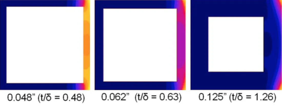
3kHz, 7500A, 20psi
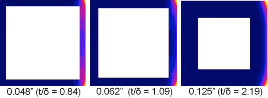
These insights demonstrate how software simulations help engineers optimize coil parameters. By balancing the wall thickness with cooling requirements, they can achieve a design that minimizes temperature stress and improves thermal durability. This helps to make more resilient coils that withstand the demands of industrial applications.
What is the result?
Optimizing induction coil design is not just about improving thermal resilience. It directly impacts operational efficiency and cost-effectiveness for manufacturing processes.
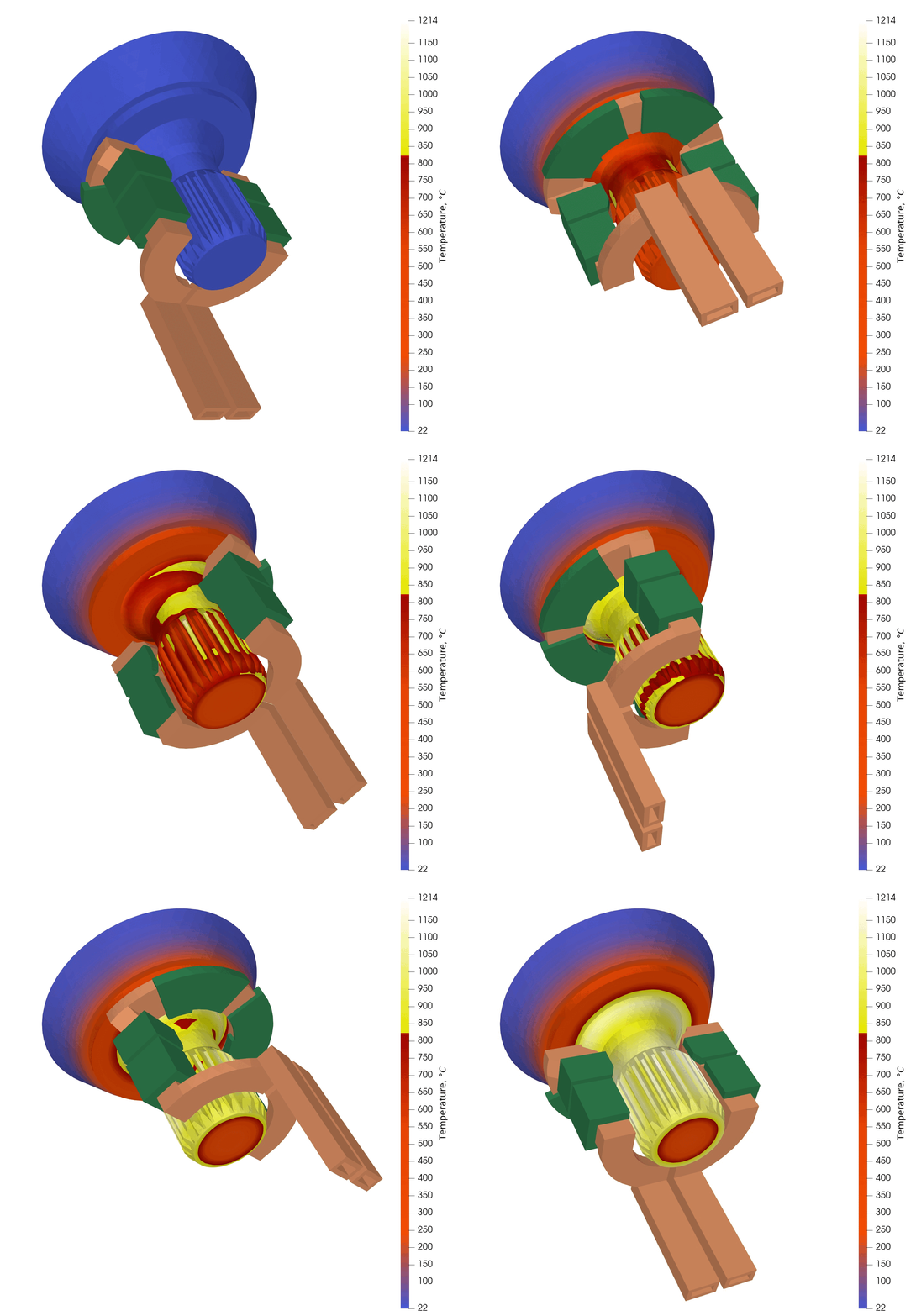
The simulation and data from the CV joint heating process demonstrate the critical impact of coil design on the efficiency and effectiveness of induction heating. You can read the single-shot hardening of the CV joint case study in our separate article.
Here’s a breakdown of the observations:
1. Effect of coil design on heating uniformity and precision
- The animation illustrates the coil design’s role in delivering heat evenly across the surface of the CV joint. The coil’s shape, positioning, and distance from the workpiece ensure precise heating zones.
- As the temperature scale shows, the targeted regions reach optimal hardening temperatures while minimizing excessive heating in non-critical areas, thus preserving material properties and reducing thermal stresses.
- This precise heating pattern is essential for parts like CV joints, where structural integrity and material hardness are important.
2. Energy efficiency and resource optimization
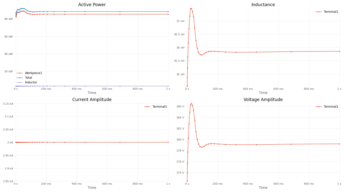
- The following graphs on active power, current amplitude, inductance, and voltage amplitude offer insights into energy usage over time.
- The Active Power graph shows that energy consumption stabilizes early in the process, suggesting that the coil’s design allows for quick heat-up to the desired temperature, maintaining energy input at an efficient level without unnecessary spikes.
- The Current Amplitude and Voltage Amplitude graphs indicate a stable current flow and voltage throughout the heating duration, showing efficient power transfer from the coil to the workpiece.
By optimizing the coil design to match the specific heating requirements of the CV joint, engineers can achieve faster heating cycles. This efficiency minimizes energy waste, reduces heating time, and allows for lower operational costs, making the process more sustainable and resource-effective.
3. Design adjustments for better performance
- The Inductance graph shows fluctuations early in the cycle before leveling out, reflecting how the coil adapts to the magnetic properties of the CV joint as it heats.
- This adaptation points to the coil’s ability to handle changing magnetic conditions, which is essential for maintaining heating efficiency.
- An optimal coil design considers these changes in inductance, allowing for a smoother energy transfer and more controlled heating process.
Why is this important for engineers?
Through the careful selection of wall thickness and cooling conditions, engineers can significantly reduce coil wear and thermal fatigue, extending coil lifespan and reducing downtime.
The case study results showed that when the wall thickness was optimized to approximately one reference depth thick, the coil achieved both high electrical efficiency and adequate cooling with minimal impact from radiation.
These findings provide engineers and manufacturing companies with a roadmap for designing coils that balance efficiency, cooling, and durability. By employing simulation-based insights, they can make informed design choices that enhance performance and reduce maintenance, ultimately driving better outcomes for high-stakes applications like heat treating and hardening.
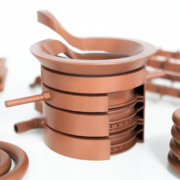
(Post illustration photo credit: PROTIQ – A Phoenix Contact Company. Unique copper inductors from 3D printing.)

