Scanning hardening of a splined shaft
Scanning hardening is promptly simulated in just 1h for a splined shaft. Geometry imported from a CAD file is processed in less than 30 min. That combined with 1h long calculation allows to find the best parameters for optimal hardening of the splined shaft.

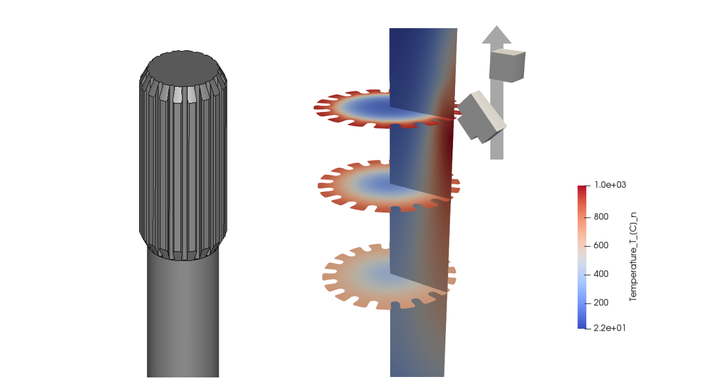
Temperature profile after 15s heating at 10 kHz, 6 kA and 10 mm/s scanning
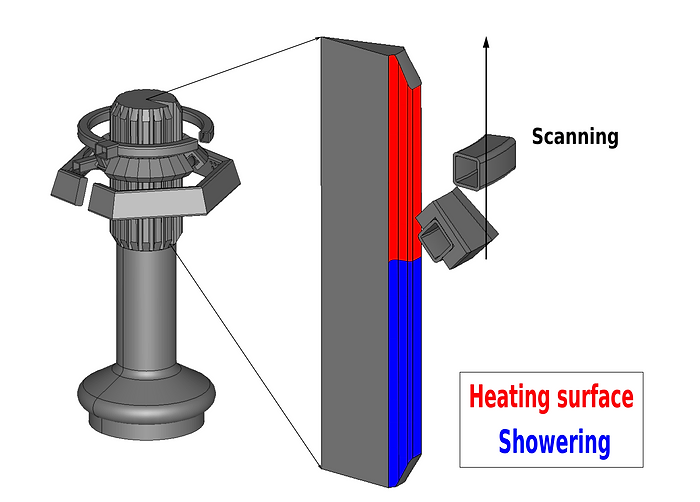
The shaft with 18 splines was simplified cutting a half-spline slice. Symmetry boundary conditions at the cut surfaces represents the full shaft.
Since the scanning case has showering next to the coil, we split the surface into the heating and showering parts defining different heat transfer coefficients there: 5 W/(m2 K) and 100 W/(m2 K) showering.

Calculation time is relatively short. Therefore, a user can carry out several simulation during a day, varying parameters such as power, frequency, scanning speed. Thus, simulation helps to come down to a valid result keeping all experiments purely in a computer.
Moreover, by definition of voltage or current source, the software calculates apparent power to keep design within limits of an available power supply.
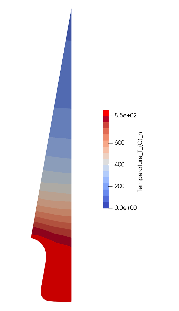
The picture illustrates the hardening profile (red) after 15s of heating at 10 kHz, 6 kA and 10 mm/s scanning with the two-turn inductor and a flux concentrator at the lower winding.
With CENOS Induction Heating simulation software, you can precisely calculate a hardening profile and choose the best combination of operation parameters within a day.

Hardening profile (red) of the spline after 15s heating at 10kHz and 6kA double-winding coil


